41
EN-US
Connecting solar module strings to the inverter (DC)
General informa-
tion about solar
modules
In order to select suitable solar modules and get the most efficient use out of the inverter,
please note the following points:
- The open circuit voltage of the solar modules increases as the temperature decreases
(assuming constant irradiance). The open circuit voltage should never rise above 600
V regardless of temperature and an irradiance of 1000 W/m².
If the open circuit voltage exceeds 600 volts, the inverter may be damaged, and all
warranty rights will become null and void.
- More exact data for sizing the solar array for the particular location can be obtained
using calculation tools such as the Fronius Configuration Tool (available at http://
www.fronius-usa.com).
- See NEC table 690.7 for the appropriate code-related voltage adjustment factor for
crystalline silicon modules, or use the manufacturer’s specified voltage coefficient.
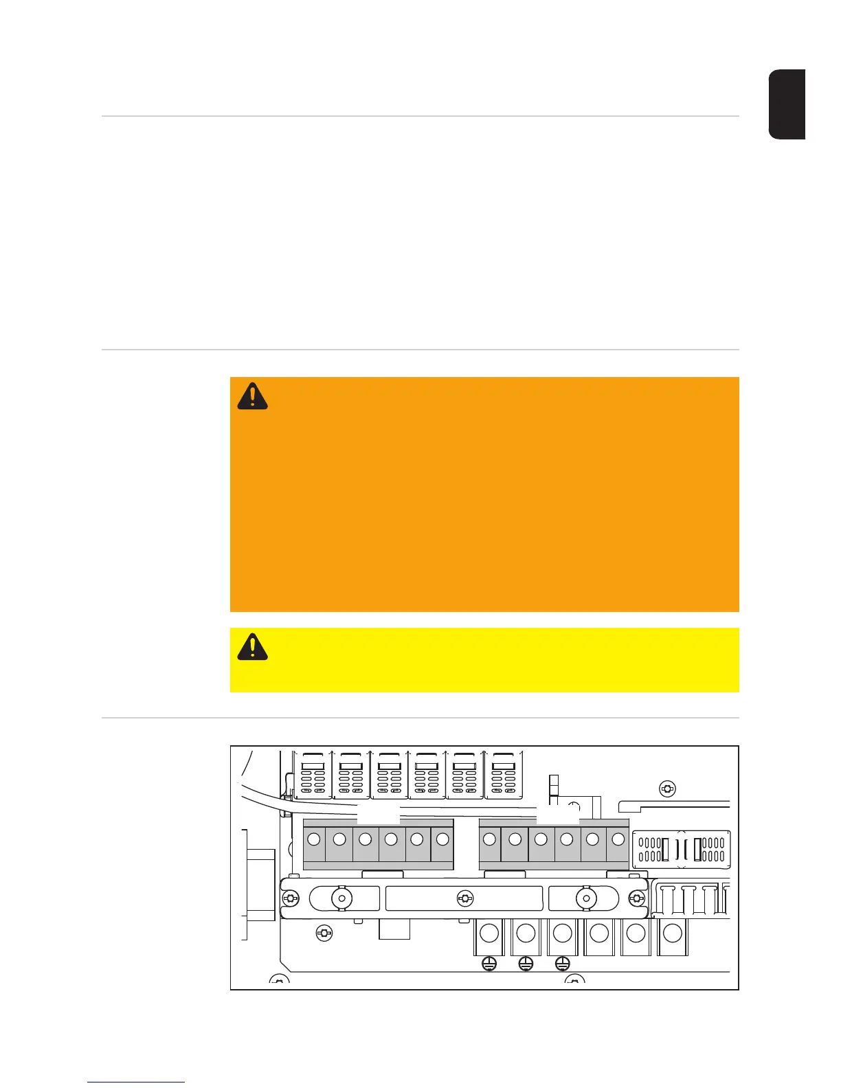
Safety
DC terminals
WARNING! An electric shock can be fatal. Danger due to grid voltage and DC
voltage from solar modules.
- The connection area should only be opened by a licensed electrician.
- The separate power stage set area should only be disconnected from the
connection area after first being disconnected from the grid power.
- The separate power stage set area should only be opened by Fronius-trained
service personnel.
Never work with live wires! Prior to all connection work, make sure that the AC
and DC wires are not charged.
The DC main switch is only used to switch off power to the power stage set. When
the DC main switch is turned off, the connection area is still energized.
CAUTION! Danger of damaging the inverter from improperly connected termi-
nals. Improperly connected terminals can cause thermal damage to the inverter
and may cause a fire. When connecting the AC and DC cables, make sure that
all terminals are tightened securely using the proper torque.
DC+
DC-

 Loading...


