38
Connecting the
Inverter to the
public grid (AC)
1 2
1 2
* Connect grid grounding / grounding conductor to the right grounding terminal
** Tightening torque:
Stranded wires 1.25 ft. lb.
Solid wires 0.81 ft. lb.
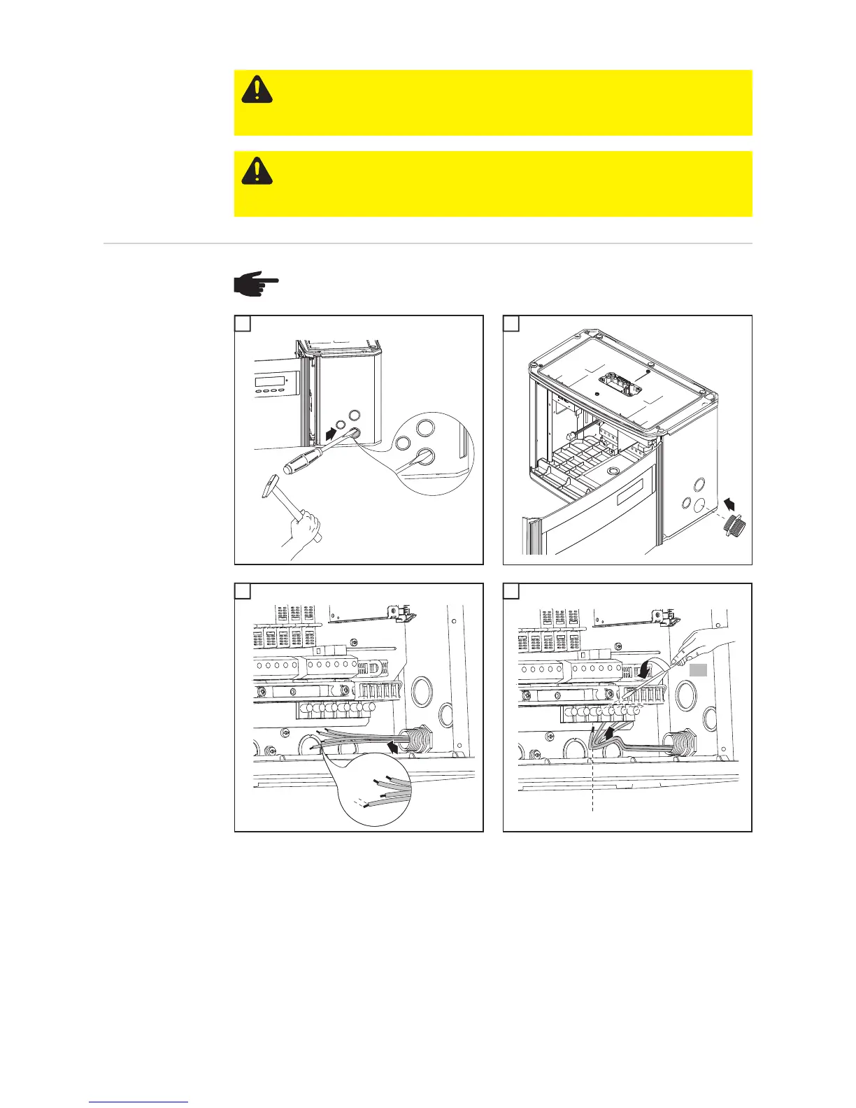
Connect the AC wires to the AC-side terminals depending on the grid and phase quantity
of the inverter:
CAUTION! Danger of damaging the inverter due to an overload of the grid neutral
conductor.
- Do not connect 2-phase and 3-phase devices to one phase
- Never operate multiphase devices in one phase
CAUTION! Danger of damaging the inverter from improperly connected termi-
nals. Improperly connected terminals can cause thermal damage to the inverter
and may cause a fire. When connecting the AC and DC cables, make sure that
all terminals are tightened securely using the proper torque.
NOTE! For outdoor installation use water tight conduit fittings and conduits only.
Conduit fittings and conduits are not part of the scope of supply for the inverter.
1
1
Conduit
2
1/2 in.
1
3
2
1
*
**
4

 Loading...


