71
EN-US
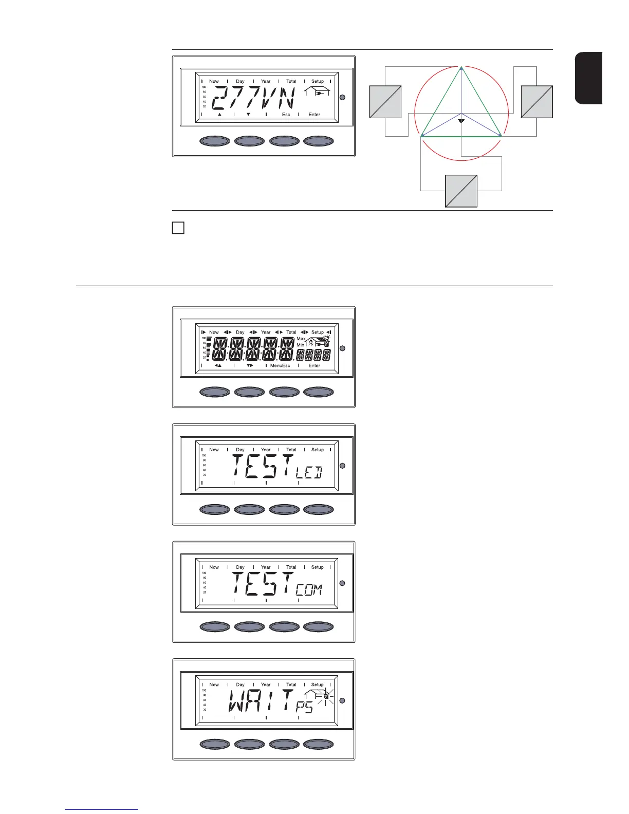
Press the 'Enter' key 2x to confirm your grid selection (or use the 'Esc' key to return to
grid selection)
The startup phase restarts with the segment test.
Startup phase
during startup op-
eration
- Segment test
All display elements light up for about
one second.
- The inverter goes through a master
check list for several seconds.
The display shows ‘TEST’ and indica-
tes the respective component that is
being tested (for example, ‘LED’)
- ‘TEST COM’ is shown.
- Synchronization with grid:
‘WAIT PS’ is displayed, the inverter
icon flashes: the inverter is waiting for
all power stage sets in the network to
be on stand-by. This procedure takes
place dependent on the DC voltage.
Grid voltage 480 V Delta: 277 V WYE
Neutral conductor available in the system
Neutral conductor monitoring is activated
277 V
277 V
277 V
120 °
12 0 °
120 °
480 V
480V
480 V
L1
L2
N
L3
=
~
=
~
=
~
2

 Loading...


