EasyManuals Logo

Fronius IG Plus A 3.0-1 UNI User Manual

Fronius IG Plus A 3.0-1 UNI
180 pages
To Next Page IconTo Next Page
To Previous Page IconTo Previous Page
Page #72 background imageLoading...
Page #72 background image
70
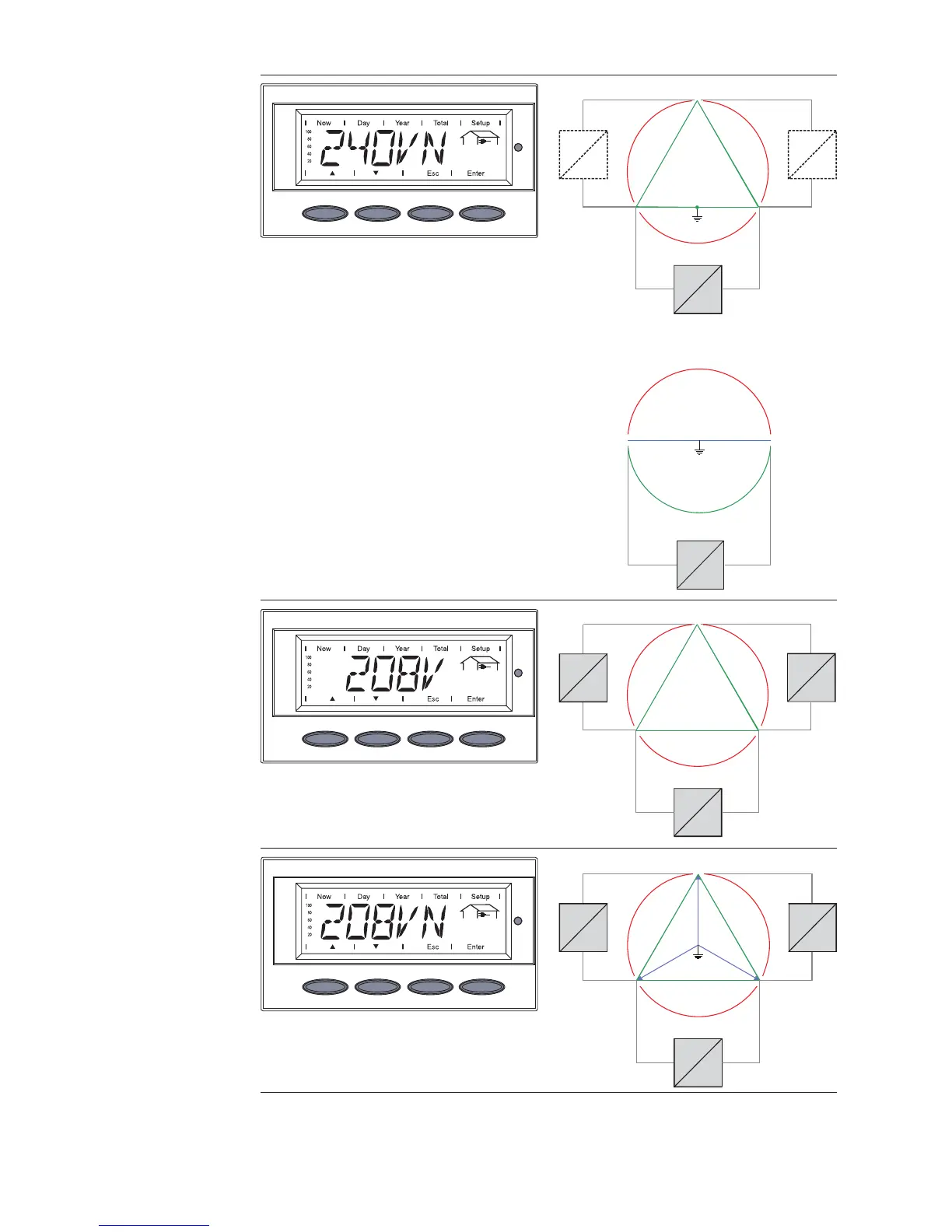
Grid voltage 240 V: 120 V Stinger
Neutral conductor available in the system
Neutral conductor monitoring is activated
Grid voltage 240 V: 120 V Split Phase
Neutral conductor available in the system
Neutral conductor monitoring is activated
Grid voltage 208 V Delta
No neutral conductor in the system
Neutral conductor monitoring is deactivat-
ed
Grid voltage 208 V Delta: 120 V WYE
Neutral conductor available in the system
Neutral conductor monitoring is activated
240 V
240 V
120 °
120 °
12 0 °
120 V12 0 V
L3
L1
N
L2
=
~
=
~
=
~
180 °
120 V 120 V
240 V
2L1L
N
=
~
120 °
120 °
12 0 °
208 V
208 V
208 V
L1
L2L3
=
~
=
~
=
~
120 V
120 V
120 V
120 °
12 0 °
120 °
208 V
208 V
208 V
L1
L2
N
L3
=
~
=
~
=
~

Table of Contents

Questions and Answers:

Question and Answer IconNeed help?

Do you have a question about the Fronius IG Plus A 3.0-1 UNI and is the answer not in the manual?

Fronius IG Plus A 3.0-1 UNI Specifications

General IconGeneral
AC nominal output3000 W
Max. apparent AC power3000 VA
Max. output current13 A
AC grid frequency50 / 60 Hz
THD<3%
Max. DC voltage500 V
Number of MPP trackers1
AC voltage range183 V - 264 V
DC input voltage range150 - 450 V
CoolingConvection

Related product manuals