43
EN-US
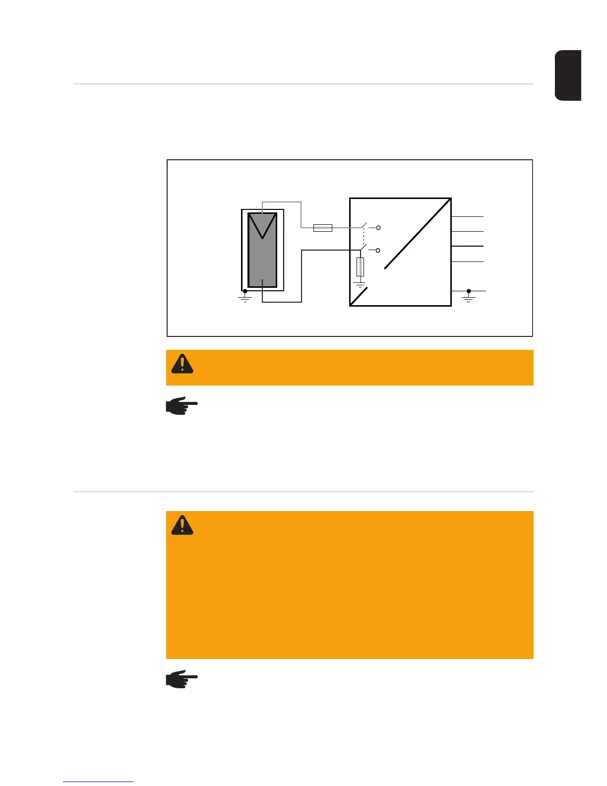
Connecting Solar Module Strings
Solar module
ground
The inverter is designed for a solar module ground at the negative pole. The solar module
ground is carried out via a fuse in the inverter.
Solar module ground at negative pole with fuse:
Wire cross sec-
tion of solar mod-
ule strings
WARNING! An electric shock can be fatal. Normally grounded conductors may
be ungrounded and energized when a ground fault is indicated. The ground fault
has to be repaired before operation is resumed.
NOTE! Do not connect the ground to the negative DC line at any point! This is al-
ready done within the inverter. If negative DC lines are connected to the DC ter-
minals or prior to this to the ground, this will circumvent the GFDI protection
system, preventing your inverter from properly detecting a fault current.
In addition, turning the DC disconnect to the OFF/open circuit condition will not
disconnect the array from ground, as it only disconnects the DC positive.
~
=
DC+
DC-
Inverter
N
L1
GND
Solar module
DC main switch
L3
L2
GFDI fuse
String fuse
WARNING! An electric shock can be fatal. Inadequately sized electrical compo-
nents can cause serious injuries to persons and damage to (or loss of) property.
- All electrical installations must be carried out in accordance with the National
Electrical Code, ANSI/NFPA 70, and any other codes and regulations appli-
cable to the installation site.
- For installations in Canada, the installations must be done in accordance with
applicable Canadian standards.
- Use minimum AWG 14, min. 167 °F (75 °C), copper wire for all grounding
wires (see NEC table 250.122).
- Use minimum AWG 14 to maximum AWG 6, min. 167°F (75°C), copper wire
for all DC wiring connections to the inverter. Voltage drop and other consid-
erations may dictate larger size wires be used.
- Use only solid or stranded wire. Do not use fine stranded wire.
NOTE! To ensure an effective strain relief device for solar module strings, only
use cable cross sections of the same size.

 Loading...


