39
EN-US
GET:
Grounding electrode terminal
N.C.:
Not used
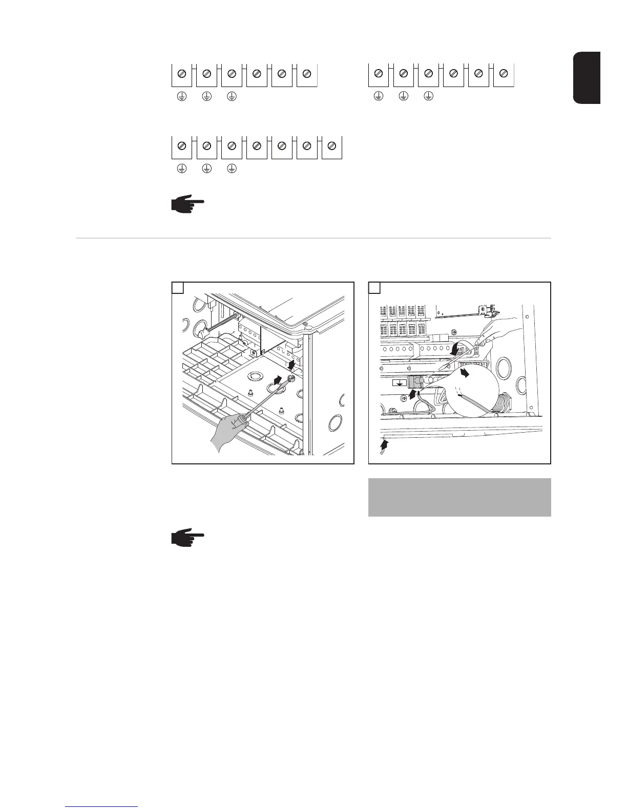
Connecting
grounding elec-
trode wire
If the photovoltaic system requires a grounding electrode, it should be connected as fol-
lows:
1 2
L1 L2 N
GET
1 phase - 208 V / 240 V
1 phase - 277 V
GET
L1 N N.C.
3 phases - 208 V / 240 V / 277 V
L1 L2 NL3
NOTE! Form a min. 4 in. wire loop using all wires.
1
2
1
4
3
1
1/2 in.
2
2
Tightening torque:
Stranded wires 1.25 ft. lb.
Solid wires 0.81 ft. lb.
NOTE! Form a min. 4 in. wire loop using all wires.

 Loading...


