49
EN-US
Safety
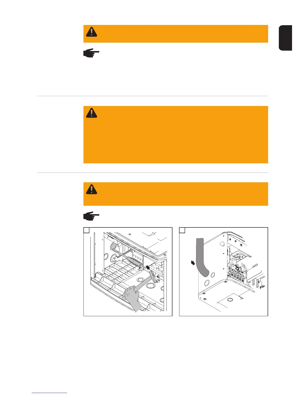
Connecting com-
bined solar mod-
ule strings using
connecting dis-
tributors
1 2
WARNING! An electric shock can be fatal. Normally grounded conductors may
be ungrounded and energized when a ground fault is indicated. The ground fault
has to be repaired before operation is resumed.
NOTE! Do not connect the ground to the negative DC line at any point! This is al-
ready done within the inverter. If negative DC lines are connected to the DC ter-
minals or prior to this to the ground, this will circumvent the GFDI protection
system, preventing your inverter from properly detecting a fault current.
In addition, turning the DC disconnect to the OFF/open circuit condition will not
disconnect the array from ground, as it only disconnects the DC positive.
WARNING! An electric shock can be fatal. Inadequately sized electrical compo-
nents can cause serious injuries to persons and damage to (or loss of) property.
- All electrical installations must be carried out in accordance with the National
Electrical Code, ANSI/NFPA 70, and any other codes and regulations appli-
cable to the installation site.
- For installations in Canada, the installations must be done in accordance with
applicable Canadian standards.
- Use copper wires for all grounding cables.
- See NEC section 250 for correct grounding.
- Use only solid or stranded wire. Do not use fine stranded wire.
WARNING! An electric shock can be fatal. Danger due to grid voltage and DC
voltage from solar modules.
The DC main switch is only used to switch off power to the power stage set. When
the DC main switch is turned off, parts of the connection area are still energized.
NOTE! For outdoor installation use water tight conduit fittings and conduits only.
Conduit fittings and conduits are not part of the scope of supply for the inverter.
1
1
1
Conduit
2

 Loading...


