44
Connecting solar
module strings
1 2
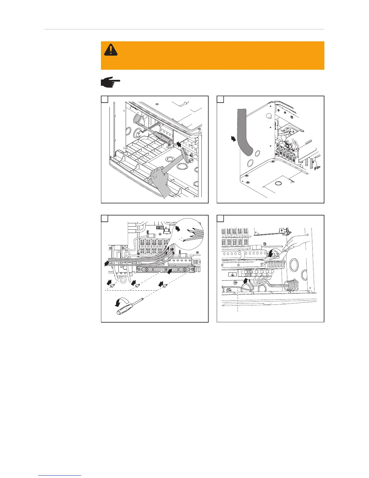
Fronius recommends the following procedure for connecting more than one solar module
strings to the DC terminals:
1. Remove metal slugs with fuse covers from the fuse holders
2. Connect solar module strings
3. Check voltage and polarity on all DC terminals in use
4. Re-insert metal slugs or correctly sized fuses
WARNING! An electric shock can be fatal. Danger due to grid voltage and DC
voltage from solar modules.
The DC main switch is only used to switch off power to the power stage set. When
the DC main switch is turned off, parts of the connection area are still energized.
NOTE! For outdoor installation use water tight conduit fittings and conduits only.
Conduit fittings and conduits are not part of the scope of supply for the inverter.
1
1
1
Conduit
2
1 1
Tightening torque:
Stranded wires 1.25 ft. lb.
Solid wires 0.81 ft. lb.
1
3
1/2 in.
2
4
5
4
6
3
2
1
*
Wire for solar module grounding
4

 Loading...


