35
EN-US
Monitoring the
Grid
Systems with
more than one in-
verter
For larger photovoltaic systems, it is possible to connect several inverters in parallel with-
out any problems. To ensure symmetrical feeding, connect the inverters uniformly to all 3
phases.
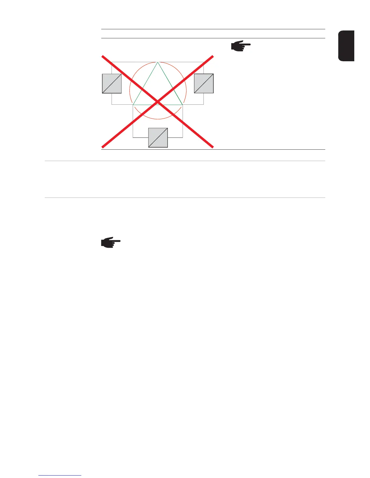
480 V Delta NOTE! Do not connect Fro-
nius IG Plus inverters to the
480 V Delta grid.
Grid Inverter
480 V
480 V
480 V
120 °
120 °
12 0 °
L1
L2L3
=
~
=
~
=
~
IMPORTANT! The resistance in the leads to the AC-side connection terminals must be as
low as possible for optimal functioning of grid monitoring.
NOTE! The inverter is designed to be connected to three-phase systems. Utilities
generally allow up to 6 kVA of unbalance, but check with your utility and try to bal-
ance the installation.
The connection to the grid should be done in the following way:
208 V / 240 V:
- Connect inverter No. 1, No. 4, No. 7, ... to L1 and L2
- Connect inverter No. 2, No. 5, No. 8, ... to L2 and L3
- Connect inverter No. 3, No. 6, No. 9, ... to L1 and L3
277 V:
- Connect inverter No. 1, No. 4, No. 7, ... to L1 and N
- Connect inverter No. 2, No. 5, No. 8, ... to L2 and N
- Connect inverter No. 3, No. 6, No. 9, ... to L3 and N

 Loading...


