EasyManuals Logo

Fronius IG Plus A 3.0-1 UNI User Manual

Fronius IG Plus A 3.0-1 UNI
180 pages
To Next Page IconTo Next Page
To Previous Page IconTo Previous Page
Page #71 background imageLoading...
Page #71 background image
69
EN-US
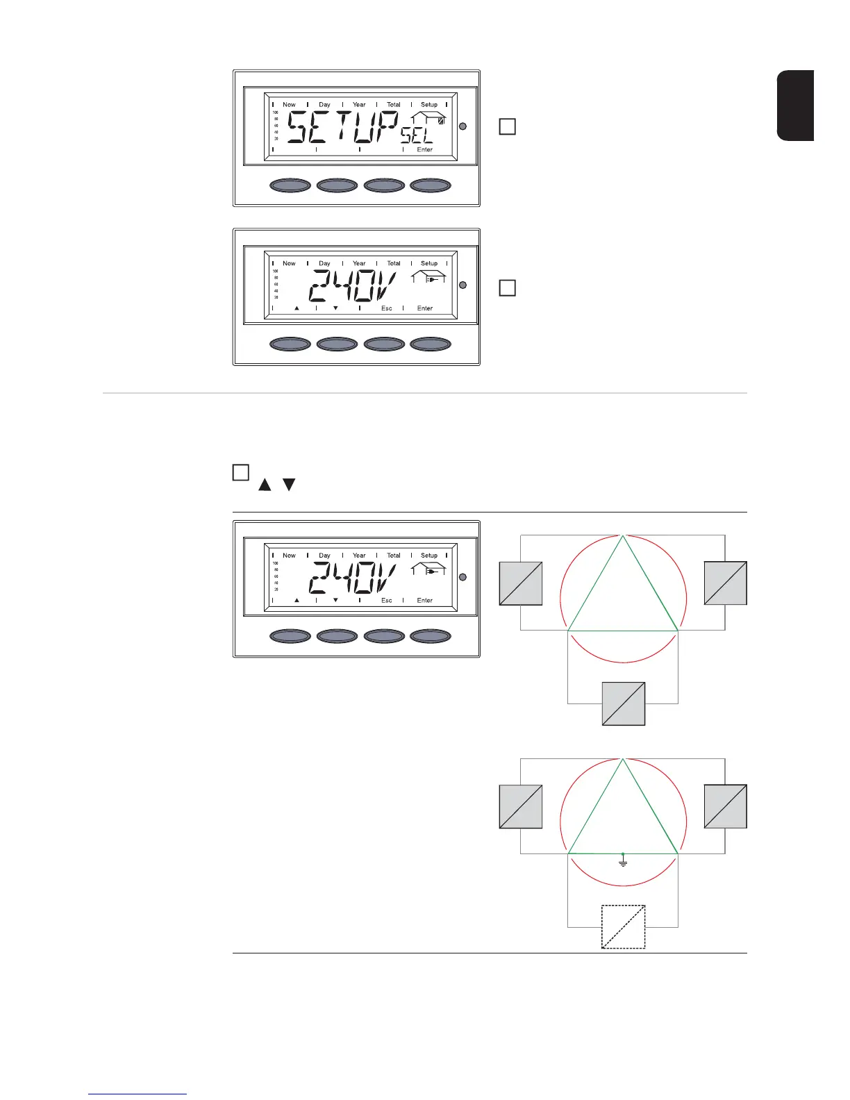
- The grid selection phase begins: 'SE-
TUP SEL' is shown.
Press the ‘Enter’ key
The first grid selection option is shown
(e.g., 240 V).
Select the grid
Selecting the grid Several grid selection options are displayed depending on the product type (see also sec-
tion 'Connecting the Inverter to the public grid’).
Use the ‘Up’ and ‘Down’ keys to select the desired grid:
3
4
Grid voltage 240 V Delta
No neutral conductor in the system
Neutral conductor monitoring is deactivat-
ed
1
240 V
240 V
240 V
120 °
120 °
12 0 °
L1
L2L3
=
~
=
~
=
~
240 V
240 V
120 °
120 °
12 0 °
120 V120 V
L3
L1
N
L2
=
~
=
~
=
~

Table of Contents

Questions and Answers:

Question and Answer IconNeed help?

Do you have a question about the Fronius IG Plus A 3.0-1 UNI and is the answer not in the manual?

Fronius IG Plus A 3.0-1 UNI Specifications

General IconGeneral
AC nominal output3000 W
Max. apparent AC power3000 VA
Max. output current13 A
AC grid frequency50 / 60 Hz
THD<3%
Max. DC voltage500 V
Number of MPP trackers1
AC voltage range183 V - 264 V
DC input voltage range150 - 450 V
CoolingConvection

Related product manuals