46
1 2
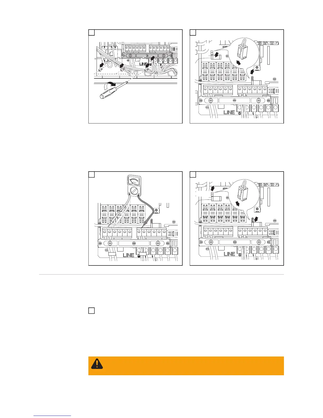
Inserting string
fuses
IMPORTANT The inverter is shipped with conductive slugs in the fuse holders. Series fus-
ing may be required depending on the type of solar module used in the system.
See NEC 690.9.
Select string fuses according to the information from the solar module manufacturer
or as per ‘Criteria for the proper selection of string fuses’ (max. 20 A per individual DC
terminal)
1 1
IMPORTANT!
- Set the jumper from the 'SMON' position to the 'SMOFF' position for correct measure-
ment results
- Check the polarity and voltage of the solar module strings: the voltage should be a
max. of 600 V, the difference between the individual solar module strings should be a
max. of 10 V.
4
1
2
2
2
3
7
3
1
2
SMON
SMOFF
8
DC+
DC-
9
3
1
2
SMON
SMOFF
10
IMPORTANT!
- Follow all solar module safety instructions
- Follow all solar module manufacturer requirements
WARNING! An electric shock can be fatal. Danger from DC voltage from solar
modules. Fuse covers are for installation purposes only. They offer no protection
against contact.
1

 Loading...


