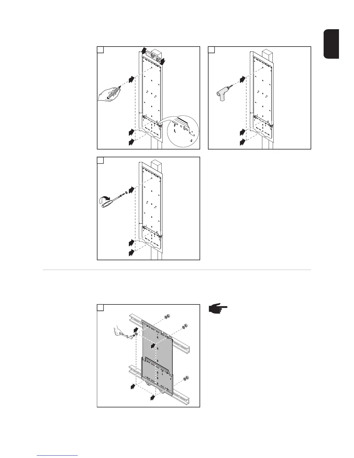
EasyManuals Logo

Fronius IG Plus A 3.0-1 UNI User Manual

Fronius IG Plus A 3.0-1 UNI
180 pages
To Next Page IconTo Next Page
To Previous Page IconTo Previous Page
Page #31 background imageLoading...
Page #31 background image
29
EN-US
1 2
3
Attaching the wall
bracket to a metal
carrier
IMPORTANT! The cut out segment marked (*) represents the placement of the inverter
display. Use this to ensure a comfortable display height for easy reading.
2
3
4
1
1
㩿㪁㪀
3
1
2
3
4
1
2
3
5
IMPORTANT! The cut out segment marked (*) represents the placement of the inverter
display. Use this to ensure a comfortable display height for easy reading.
1
NOTE! When installing using a
metal carrier, the inverter should
not be exposed to rainwater or
water spray at the back. Ensure proper
rainwater or spray water protection.
1
4 x
3
4
22
(*)
1

Table of Contents

Questions and Answers:

Question and Answer IconNeed help?

Do you have a question about the Fronius IG Plus A 3.0-1 UNI and is the answer not in the manual?

Fronius IG Plus A 3.0-1 UNI Specifications

General IconGeneral
AC nominal output3000 W
Max. apparent AC power3000 VA
Max. output current13 A
AC grid frequency50 / 60 Hz
THD<3%
Max. DC voltage500 V
Number of MPP trackers1
AC voltage range183 V - 264 V
DC input voltage range150 - 450 V
CoolingConvection

Related product manuals