68
Commissioning
Factory pre-set
configuration
The inverter has been pre-configured in the factory and is ready for operation. You only
have to set the available power grid for startup.
To change your inverter settings, please see section ‘The setup menu’ in the chapter ‘Op-
eration.’
Requirements for
start-up operation
- Inverter connected to the public grid (AC)
- Inverter connected to solar modules (DC)
- 3 plastic dividers inserted
- 2 metal covers mounted
- Power stage set mounted
Commissioning
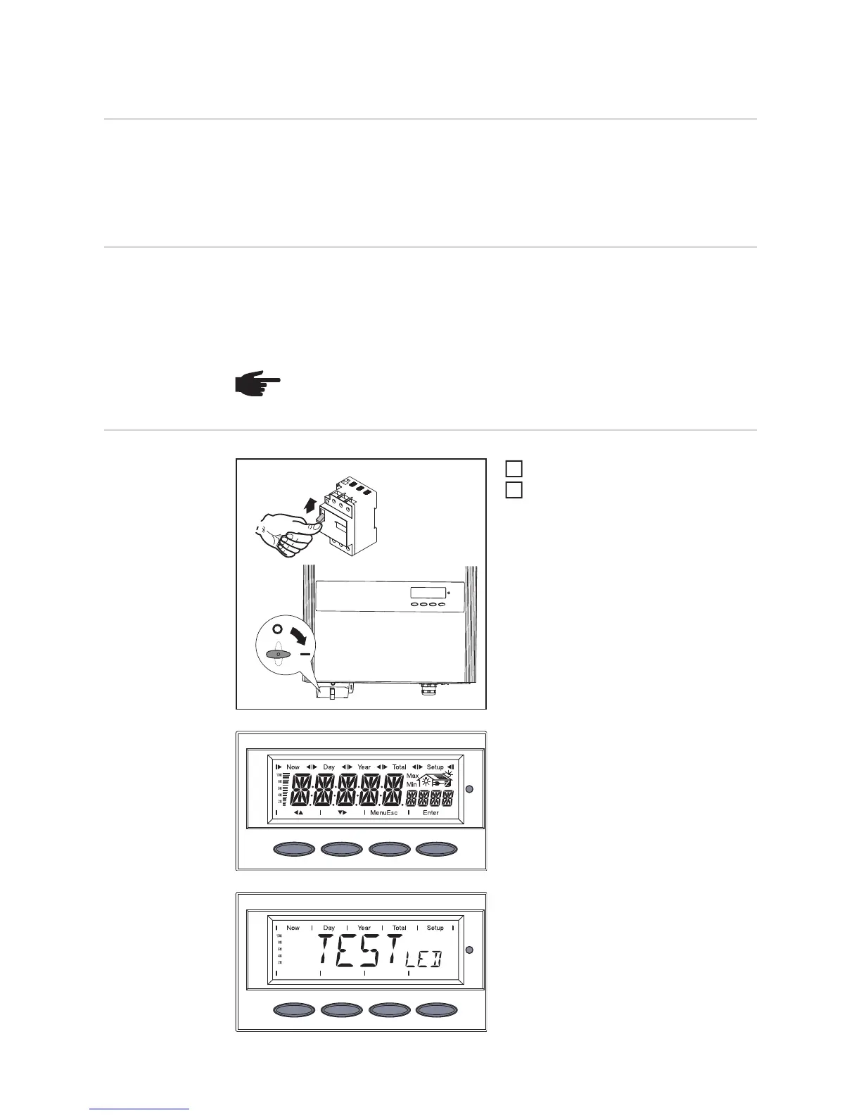
Turn on AC disconnect
Flip DC main switch to position - 1 -
As soon as the photovoltaic modules pro-
duce sufficient power, the Operating Status
LED lights up orange.
The orange LED indicates that the feed-in
mode of the inverter will begin shortly.
The screen displays the startup phase.
- Segment test
All display elements light up for about
one second.
- The inverter goes through a master
check list for several seconds.
The display shows ‘TEST’ and indica-
tes the respective component that is
being tested (for example, ‘LED’).
NOTE! Do not operate the inverter without fuse covers.
off
on
1
ON
AC
2
ON
OFF
1
2

 Loading...


