36
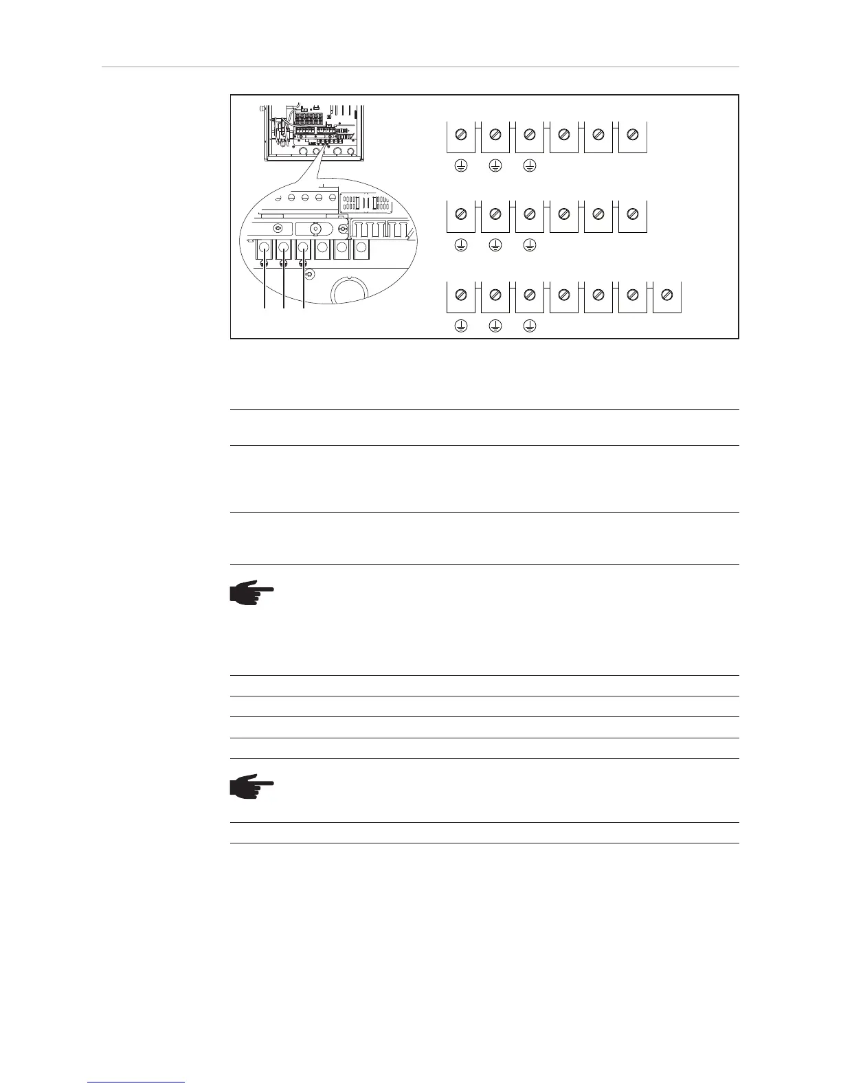
AC-side terminals
and grounding
terminals
The terminals are designed for the following terminal connections:
Max. wire cross section AWG 4
Grounding terminals:
(1) Grounding Electrode Terminal (GET)
A grounding electrode terminal may be required depending on local regulations.
(2) Grounding of photovoltaic components (e.g., solar module frames)
The ground for photovoltaic components such as solar module frames must be
connected at the grounding terminals. The size of the wire usually corresponds to
the largest wire in the DC system.
(3) Grid grounding / Grounding conductor
The inverter must be connected via the grounding terminal to the AC grid ground-
ing.
NOTE!
- Use copper wires for all grounding cables
- Use only solid or stranded wire. Do not use fine stranded wire.
- See NEC section 250 for correct grounding.
AC-side terminals:
L1 = Phase conductor L1
L2 = Phase conductor L2
L3 = Phase conductor L3
N = Neutral conductor N
NOTE! The neutral conductor is not bonded to ground internally.
NC = Not connected
(1)
(2)
(3)
1-phase inverters 208 V / 240 V
1-phase inverters 277 V
3-phase inverters 208 V / 240 V / 277 V
L1
L2 N
N.C.
L1
N
L3
L1
L2
N
GET
GET
GET

 Loading...


