EasyManuals Logo

Fronius IG Plus A 3.0-1 UNI User Manual

Fronius IG Plus A 3.0-1 UNI
180 pages
To Next Page IconTo Next Page
To Previous Page IconTo Previous Page
Page #52 background imageLoading...
Page #52 background image
50
The DC Voltage must not exceed 600 V, re-
gardless of temperature.
1 1
Tightening torque:
Stranded wires 1.25 ft. lb.
Solid wires 0.81 ft. lb.
2
4
3
5
1
DC+
3
4
1/2 in.
2
1
3
*
Wire for solar module grounding
4
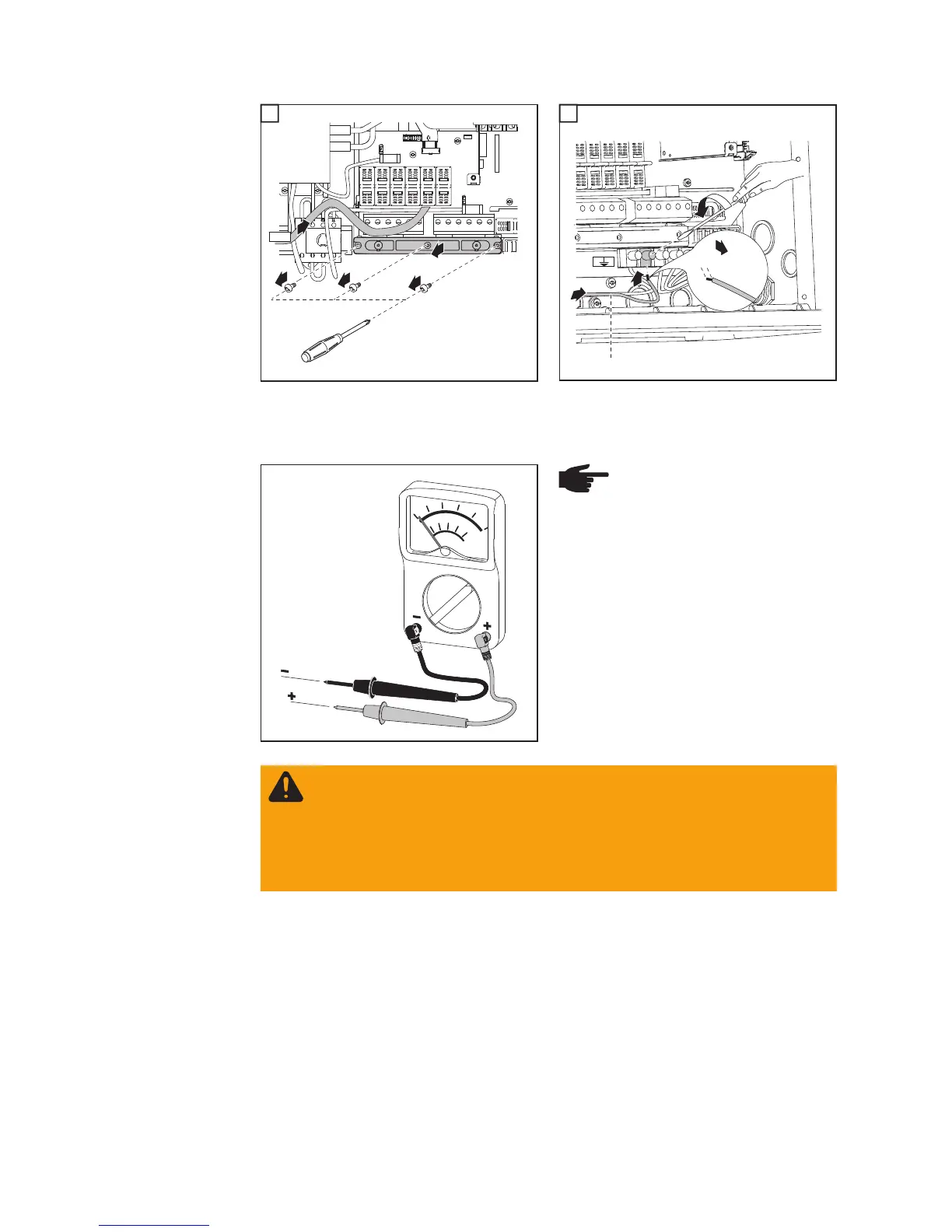
NOTE! Connecting the DC wiring
with the wrong polarity may cause
damage to the inverter. Check
both the polarity and the open cir-
cuit voltage.
WARNING! An electric shock can be fatal. Danger due to DC voltage from solar
modules.
Once solar module strings are connected using connecting distributors, the lower
clips of the fuse holders are energized (even with the DC main switch in the off
position).
Before commissioning the inverter insert metal slulgs with fuse covers into the
fuse holders.

Table of Contents

Questions and Answers:

Question and Answer IconNeed help?

Do you have a question about the Fronius IG Plus A 3.0-1 UNI and is the answer not in the manual?

Fronius IG Plus A 3.0-1 UNI Specifications

General IconGeneral
AC nominal output3000 W
Max. apparent AC power3000 VA
Max. output current13 A
AC grid frequency50 / 60 Hz
THD<3%
Max. DC voltage500 V
Number of MPP trackers1
AC voltage range183 V - 264 V
DC input voltage range150 - 450 V
CoolingConvection

Related product manuals