56
1
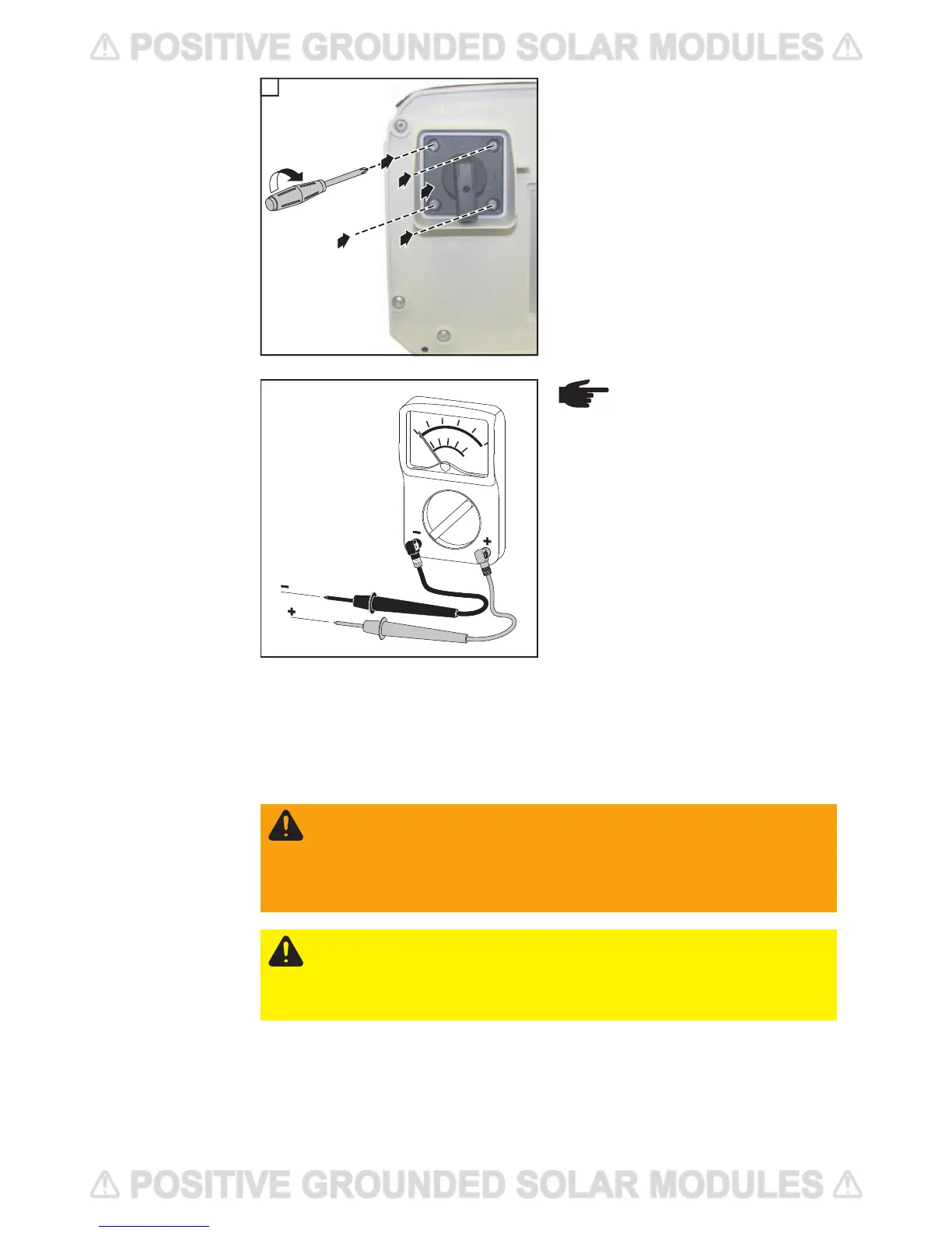
- Insert switch plate and switch knob (1)
- Fix switch plate and switch knob using
4 screws (2-3-4-5)
Tightening torque: 2.21 ft. lb.
The DC Voltage must not exceed 600 V, re-
gardless of temperature.
Fronius recommends the following procedure for connecting more than one solar module
strings to the DC terminals:
1. Remove metal slugs with fuse covers from the fuse holders
2. Connect solar module strings
3. Check voltage and polarity on all DC terminals in use
4. Re-insert metal slugs or correctly sized fuses
2
2
4
3
5
1
11
NOTE! Connecting the DC wiring
with the wrong polarity may cause
damage to the inverter. Check
both the polarity and the open cir-
cuit voltage!
WARNING! An electric shock can be fatal. Danger due to DC voltage from solar
modules.
Once a solar module string is connected, the lower clip of the respective fuse
holder is energized (even with the DC main switch in the off position).
Before commissioning the inverter insert metal slulgs or correctly sized fuses with
fuse covers into the respective fuse holder.
CAUTION! Danger of damaging the inverter by overload.
- Only connect a maximum of 20 A to an individual DC terminal.
- Connect the DC+ wire to the right connection of the inverter's DC terminals.
- Connect the DC- wire to the left connection of the inverter's DC terminals.
- Identify the reversed polarity with (+) and (-) according to step 14

 Loading...


