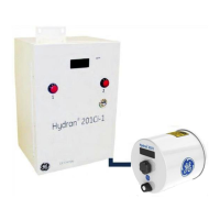
When removing the CPU module, make sure not to bend the
pins of the connector located between the CPU and I/O
modules.
7.3.2.2 Separating the Brass Adapter from the Heating Plate
1. Disconnect the Hydran 201 sensor’s connector.
2. Remove the six 1/4-28 cap screws from the adaptor using the supplied 3/16-in
Allen key.
3. Separate the adaptor and the heating plate.
4. Protect the adaptor’s threads with the supplied plastic cap.
7.3.2.3 Removing the Hydran 201 Sensor
1. Unscrew the sensor to separate it from the brass adaptor.
2. Inspect the sensor’s membrane by looking at it. Its surface must be flat, without
cuts or tears.
3. Protect the sensor’s membrane by placing the supplied plastic cap over the
sensor’s threads.
7.3.2.4 Conclusion
1. Store the parts, the brass adaptor and the Hydran 201 sensor in a box and in a
safe place until ready for installation.
2. Compare the contents to the list in Section 7.1.2.
Note: If the Hydran 201Ti has been in storage for more than six months, the battery
located inside the cover of the CPU module might be disconnected, as recommended
by General Electric. Reconnect the battery before installation; procedures to
disconnect and reconnect the battery are given in Section 3.7.3 & 3.7.4.
7.3.3 Preparing the Valve
1. Wipe the inside of the valve.
2. Clean the valve’s threads.
3. Wipe up any trace of oil and dispose of the collected oil according to company
standards.

 Loading...