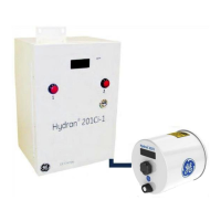
• Flexible rather than rigid conduits should be used near the H201Ci-C to ease
installation and servicing.
• Conduits, or cable armors, should be made of steel to shield against magnetic
fields.
The procedure is as follows:
1. Remove the rubber plugs from the required openings of the H201Ci-C enclosure.
2. For each cable being used, install a standard, watertight conduit fitting (not
supplied). Up to eight conduits may be installed (supervisory links, AC power
supply).
3. Mount a conduit to each fitting.
4. Ground the conduits and/or cable shields at some point. Follow the company
regulations meticulously.
8.3.4 Installing the Supervisory Link Cables
Note: The supervisory link cables have already been run into conduits up to the
Hydran 201Ci-C if the installation of the Hydran 201Ti’s is completed (see Section
7.3.9).
1. If required, trim the excess length from the end of the supervisory link cables to
be wired into the H201Ci-C.
Note: The total maximum length of all supervisory link cables connected to one
H201Ci-C is 1,200 m (4,000 ft).
2. Ensure the four wires of each cable have been labeled (for identification purposes)
at both ends.
3. Connect the wires and shield of one cable to one of the four H201Ci-C’s
termination boards. For wiring details, see Table D - 8 in Appendix D.
Note: The shield is grounded through a capacitor at the H201Ti end to protect against
radiofrequency interference. Shields must also be directly grounded at the H201Ci-C’s
termination board.
The H201Ci-Cs operation may be affected if wires are not
connected correctly. Be careful when installing and inserting
each wire. Be sure to insert all strands in the terminal; strands
that touch two terminals cause problems. Strip each wire to a
maximum of 8 mm before installing it. Do not leave trims of
metallic strands inside the H201Ci-Cs enclosure

 Loading...