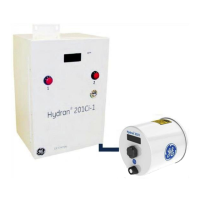
Hydran* 201i Instruction Manual
MA-033 Rev. 14.0, 12-Nov-18
14.8 Hydran 201Ci Controller Verification
Frequency: Annually or on fail alarm
Note: Alarms are triggered during this verification procedure. Please warn the
appropriate personnel.
The H201Ci is verified as follows:
1. Check for water or dust infiltration inside the enclosure.
2. If necessary, clean and fix the enclosure.
3. Check for loose connections on the terminal blocks and connectors. Retighten if
necessary.
AC power supply voltage is present on most terminals.
4. Verify the LED’s, the heater and the display by performing the procedure in
Section 9.2.2.
5. Verify the Hydran 201Ci-1’s analog output by performing the procedure in Section
9.2.3.
6. If the H201Ci-1 is not currently in operation and if its alarm contacts are used
(connected to a SCADA system), verify the alarm indicators and relays by
performing the procedure in Section 9.2.4.
7. Verify the RS-232 or USB and RS-485 communications by performing the
procedure in Section 8.2.3.
14.9 Fuse
The Hydran 201Ti, the Hydran 201Ci-C and the Hydran 201Ci-1 require the following
type of fuse:
• 5 A
• 250 VAC
• 5 x 20mm
• Slow blow / Time delay

 Loading...