• In the H201Ti: To the Supervisory Link and Analog Output Termination Board
(item 9 in Figure 3-4).
• In the H201Ci-C: To the terminals 21 to 24 of the Main Terminal Block (item 5
in Figure 4-2).
• In the H201Ci-1: To the terminals 21 to 24 of the Main Terminal Block (item 6
in Figure 4-6).
10.1.1 TDM Pulse
The TDM pulse is used only with the Hydran 201Ci-1 Controller to transfer two pieces of
information from the Hydran 201Ti to the H201Ci-1 itself:
• Actual dissolved gas level: This analog signal varies from 0 to 100% (0 to
2,000ppm) with a resolution of 1 part in 4,000.
• Alarm relays status: This digital information has four possible values, namely
Normal, High, High-High and Fail.
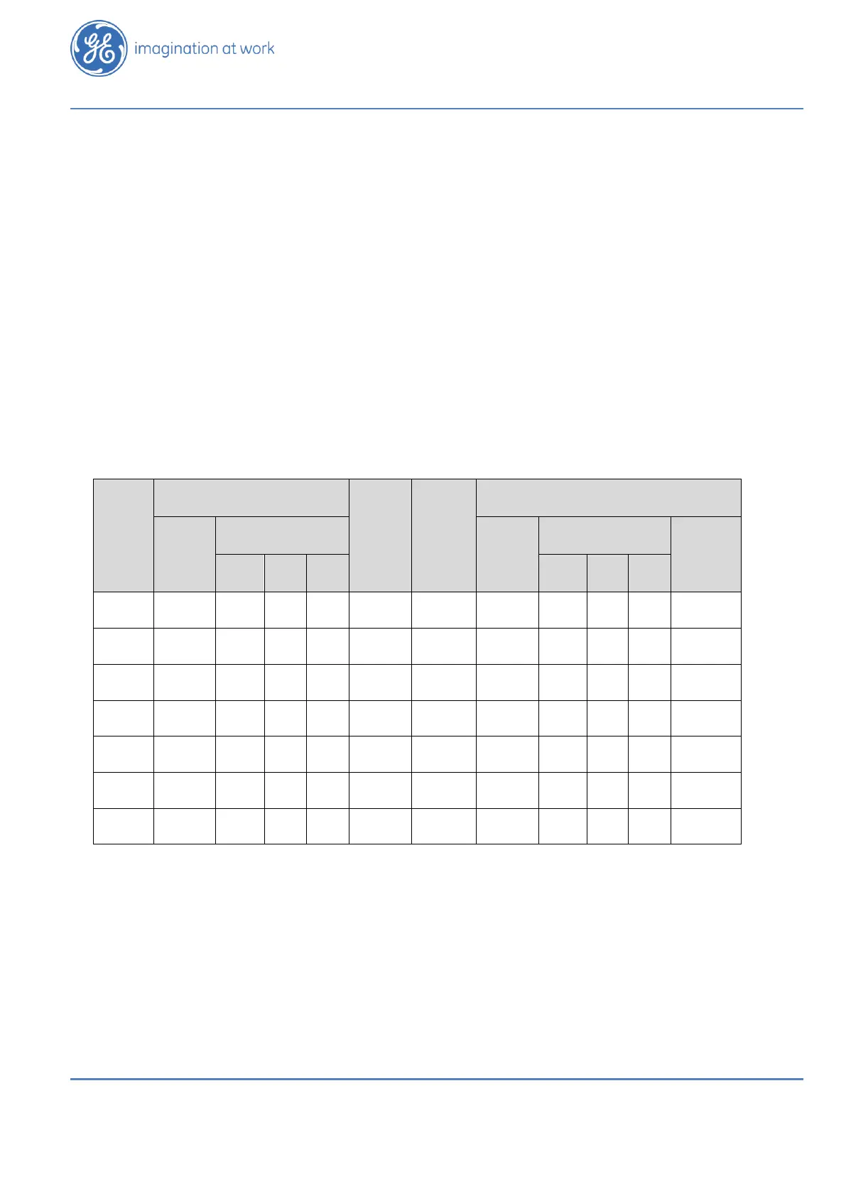
The relationship between the alarm relay states and the status of the H201Ti, of the TDM
signal and of the H201Ci-1 is shown in Table 10-1 below.
a. - = without consequence; H = High Alarm; HH = High-High Alarm; Sup = Supervisory.
b. On = Normal (no alarm); Off = Alarm
Table 10-1: Alarm Relay States and Status of the H201Ti, TDM Signal and H201Ci-1

 Loading...


