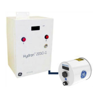
4 HYDRAN 201CI CONTROLLERS
4.1 Hydran 201Ci-C Communications Controller
Figure 3-1 shows one possible configuration of a Hydran 201i System. It consists of
three components:
• A host computer.
• The Hydran 201Ci-C Communications Controller, which is described here.
• The Hydran 201Ti Intelligent Transmitter, already described in Chapter 3.
Figure 4-1: Typical Configuration of a Hydran 201i System
4.1.1 Features
The Hydran 201Ci-C is meant specifically to interface a network of up to 128 Hydran
201Ti ’s to a computer via a single RS-232 or USB link, or an optional modem. As opposed
to the Hydran 201Ci-1 (Section 4.2), the H201Ci-C does not have a display, nor does it
provide alarms or analog outputs.
Up to four H201Ti’s (typically, a transformer bank [A, B, and C] and sometimes an
auxiliary) can be connected to each H201Ci-C through the isolated supervisory link. A
maximum of 32 H201Ci-C’s (and/or Hydran 201Ci-1s) can be networked via an RS-485
Local Area Network (LAN).
The H201Ci-C features:
• A digital circuit board to control all communications, including networking.
• A terminal block to connect the ac power supply.
• A terminal block to connect the H201Ci-C and the H201Ti’s with a supervisory link.
• Connectors for the communication cables:
- RS-232 or USB link toward a host computer or a modem.
- RS-485 link toward other H201Ci Controllers to establish a network.

 Loading...