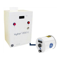
Note: The Hydran 201Ci -C does not have alarm relays. The H201Ci-1 alarm relays are
more accessible than the H201Ti’s relays. Generally, the H201Ci-1 alarm relays are the
ones connected to an alarm panel or SCADA system.
11.2.1 Alarm Contacts
Each relay has:
• A normally open (NO) contact.
• A normally closed (NC) contact.
• A common contact (Type C).
The physical form of these contacts is as follows:
• Hydran 201Ti: See the Alarm Contacts 9-Terminal Block (item 12 in Figure 3-5).
• Hydran 201Ci -1: See the terminals 7 to 15 of the Main Terminal Block (item 6
in Figure 4-6).
• Hydran 201Ci-C: Does not have alarm relays and thus no alarm contacts.
11.2.2 Status of Alarm Relays
The gas High and High-High alarm relays can only be in two states:
• On (coil energized, alarm state LED’s turned on).
• Off (coil de-energized, alarm state LED’s off).
Note: The relays of the Hydran 201Ci Controller always adopt the state of the Hydran
201Ti’s corresponding relay (except if the supervisory link is broken, in which case the
H201Ci triggers a fail alarm, regardless of the H201Ti’s fail alarm relay). As far as the fail
alarm relay, the coil is energized in normal operation (no alarm).
Table 10-1 lists the possible states of all relays. The state of each relay can be
determined as follows:
• H201Ti:
- By displaying RelayH State, RelayHH State and SysOk State in the
Relays/Analog submenu.
- By looking at the LED’s on the right side of the I/O module (see Figure 3-7)
- By verifying the state of the alarm contacts on the Alarm Contacts 9-
Terminal Block (item 12 in Figure 3-5).
• H201Ci-1:
- By looking at the LEDs on the circuit board (see items 13 to 18 in Figure 4-
7)

 Loading...