4.1.4 Additional Information
To obtain more information on the Hydran 201Ci-C, please consult the following parts of
this manual:
• Before the installation: See Chapter 6.
• Installation: See Chapter 8.
• Communications and networking: See Chapter 10.
• Operation: See Chapter 12.
• Troubleshooting: See Chapter 13.
• Maintenance: See Chapter 14.
• Technical specifications: See Appendix A.2.
• Mechanical drawing: See Appendix B.2.
• Functional block diagram: See Appendix C.2.
• Terminal blocks and connectors: See Appendix D.2.
4.2 Hydran 201Ci-1 One Channel Controller
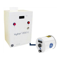
Figure 3-4 below shows a Hydran 201R Model i. It consists of two components:
• The Hydran 201Ci-1 One-Channel Controller, which is described in detail in
Section 4.2.
• The Hydran 201Ti Intelligent Transmitter, already described in Chapter 3.
4.2.1 Features
The Hydran 201Ci-1 is designed to supervise one Hydran 201Ti and be used as an
interface between this H201Ti and a host computer.
The H201Ci-1 features:
• A numerical display that indicates the dissolved gases-in-oil level in parts per
million (ppm), measured by the connected H201Ti.
• Two gas alarm contacts (High and High-High).
• One Fail alarm contact.
• Two illuminated push-buttons (alarm indicators) mounted on the door.
• One isolated, analog 4–20 mA output.
• A digital/analog circuit that controls all communications and also the display,
analog outputs and alarm functions.

 Loading...