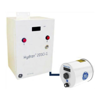
Note: The TDM pulse signal from the H201Ti (which uses a third pair when the
supervisory link is connected to an H201Ci-1) is not used by the H201Ci-C. The TDM
pulse signal only carries analog data and relay status, and it is not required for
communications and networking functions.
13. Heater Indicator, Yellow (DS8): This LED indicator is lit when the enclosure heater
is On. The enclosure temperature is controlled and the heater periodically turns
on and off to maintain the temperature near 25°C (77°F).
14. Supervisory Link Connector to Termination Board No. 2, 4 Pins (J12): See item 12
above.
15. Supervisory Link Supply Indicator, Green (DS12): This LED indicator is lit when the
supervisory link power supply is On.
16. Supervisory Link Connector to Termination Board No. 3, 4 Pins (J13): See item 12
above.
17. Supervisory Link Connector to Termination Board No. 4, 4 Pins (J14): See item 12
above.
18. AC Supply Fuses (F11): There is one fuse holder for standard 5 x 20 mm fuses (the
rating can be found in Section 14.9).
19. AC Supply Connector, 3 Pins (J2): The AC line is factory-wired from the AC
terminal block to this connector.
20. Heater Connector, 6 Pins (J3): The enclosure heater is factory-wired to the
connector J3. It consists of two 50-W resistors located under the support bracket
of the electronic circuit board.
21. Voltage Selector Switch (SW1): For wiring details, see Table D - 9 in Appendix D.
This selector is used to choose between the following:
• 115 V, corresponding to 100–120 VAC 50/60 Hz
• 230 V, corresponding to 200–240 VAC 50/60 Hz
22. Configuration Communication Status Indicator, Yellow (DS7): This LED, only used
for programming purposes at the factory, indicates there is a configuration of the
unit through one of the serial ports. It flickers as data bits pass through the
H201Ci-C, whatever the direction and the port (RS-232, RS-485 LAN, USB or
optional modem).
23. Communication Status Indicator, Yellow (DS6): This LED indicates that serial
communication activity is present. It flickers as data bits pass through the
H201Ci-C, whatever the direction and the port (RS-232, RS-485 LAN, USB or
supervisory link).

 Loading...