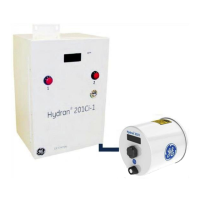
Table 11-1: Alarm Conditions Monitored by the Hydran 201Ti
a. Either one of the following cables (or connectors in the connection link): Sensor, sensor thermistor, or
heating plate thermistor.
11.1.2 Purpose of Hourly and Daily Trends
Detection of hourly and daily trend alarm conditions is a unique feature of the
Hydran 201i System that provides early warning of slowly increasing gas level. For
example, let us consider a transformer with a 50-ppm gas level and a typical gas High
alarm set point of 150 ppm.
• If no trend alarm is used and if the gas level reading starts increasing at the
rate of 50 ppm per month, it takes two months before the gas High alarm
condition is detected and the investigation of the possible causes of the
increase begins (unless the gas reading was already closely monitored).
• If the daily trend High alarm is used and its alarm set point is adjusted to
25ppm, its period to 30 days and its alarm delay to 33% of the period
(10 days), the alarm would occur approximately 23 days after the beginning of
the gas level increase. Investigation of the possible causes could thus start
five weeks earlier. For details on trend computations, see Section 11.4.3.
11.2 Alarm Relays
The Hydran 201Ti and the Hydran 201Ci-1 both have three alarm relays, in other words
one relay per alarm level:
• One gas High alarm relay.
• One gas High-High alarm relay.
• One fail alarm relay, referred to as System in the H201Ti’s menus.

 Loading...