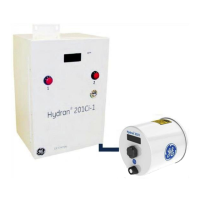
Figure 4-4: Hydran 201R Model i
• Network and communication management. The H201Ci-1 (or any other Hydran
201Ci Controller in a local network) is connected to the host computer with an RS-
232 or USB link or a modem (optional) and to each H201Ti with a supervisory link.
A maximum of 32 H201Ci Controllers (H201Ci-C and/or H201Ci-1) can be
connected together with an RS-485 link to establish a local network that can
contain up to 128 H201Ti’s. For details on network configurations, see Chapter
10.
• A terminal block to connect the following components:
- AC power supply
- Supervisory link between the H201Ci-1 and the H201Ti
- RS-485 link toward other H201Ci controllers to establish a network
- Alarm contacts (High, High-High and fail)
- Isolated, analog output
• Connectors for the RS-232 or USB link toward a host computer.

 Loading...