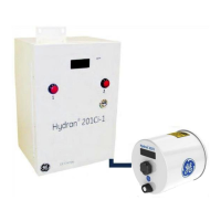
Hydran* 201i Instruction Manual
MA-033 Rev. 14.0, 12-Nov-18
Microprocessor; watchdog; clock
Real-time operating system; menu-driven interface
- Gas level, hourly trend and daily trend readings
- Gas level and gas trends an fail alarms
- History data logging (Short Term, Long Term, Events and
Service)
- Periodic sensor test
- Calibration, configuration and self-test
- Networking
- Remote embedded software upgrading
- Remote control via Hydran 201Ci Controller (optional
modem)
- Hydran protocol or ModBus protocol over Supervisory link
(RS-485)
User selection (one port at a time):
USB Type B female connector for host computer
Supervisory link to connect to PC or H201Ci Controller
Backlit liquid crystal display (LCD); 2 lines x 16 characters
Keypad 6 keys: Enter, Up, Down, Change, Esc and End
Gas High, Gas High-High and System Fail
One NO and one NC contact (type C) per alarm
Resistive load: 3A @ 250 VAC; 3A @ 30 VDC
Isolated 4–20 mA; 0–2,000 ppm range; isolation 2,000 Vac RMS;
10 V load maximum; 500-ohm @ 20 mA
Type NEMA 4X; white, cylindrical aluminum housing; 186mm
(7.3in) diameter x 180 mm (7-1/8 in)
Totally enclosed CPU and I/O electronics
Enclosure
Heating/Cooling
300-W heating plate; convection cooling; maintain unit between
15 and 65°C (59 and 149°F)
With 1.5-in male NPT threads (standard); mounting on

 Loading...