Disassembly
Removing the LCD
Step 1
Place the TympStar in its normal orientation and rotate the LCD forward to
expose the screw holes in the back of the LCD enclosure.
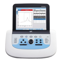
Step 2
Remove the six screws that secure the
back cover to the LCD enclosure.
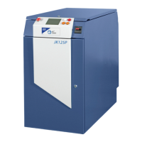
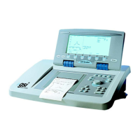
Step 3
Gently lift the LCD back cover
straight off the LCD enclosure.
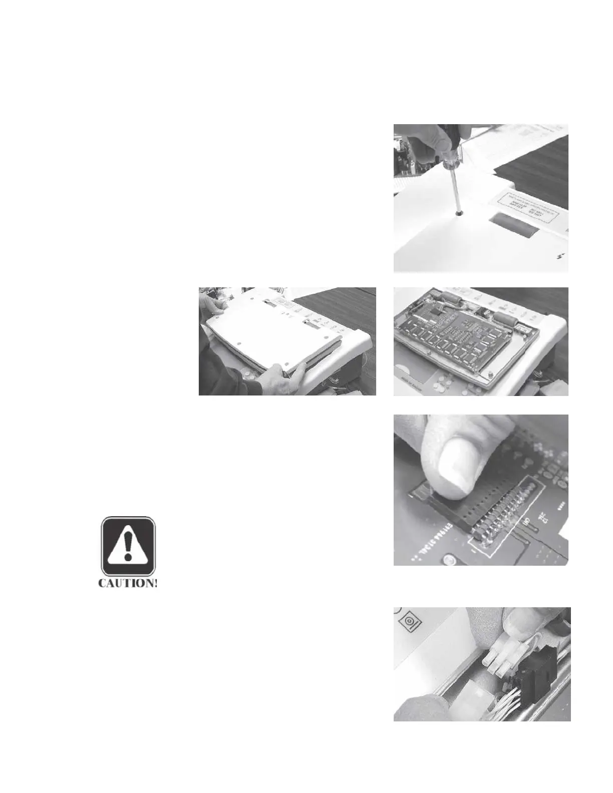
Step 4
Disconnect the 12-pin cable connec-
tor from the LCD assembly by grasp-
ing the connector firmly and gently
pulling it straight off the pins.
Gently
rock the connector back and forth as
it is pulled off the pins.
CAUTION
The brown cable wire should be
connected to pin 1 on the board
when the cable is re-installed.
Step 5
Unplug the white cable connector near
the hinge assembly.
GSI TympStar Version 1 and Version 2 Service Manual
5 - 25
 Loading...