1. Before Connecting to PLC 1-7
Connection between MJ2 and PLC
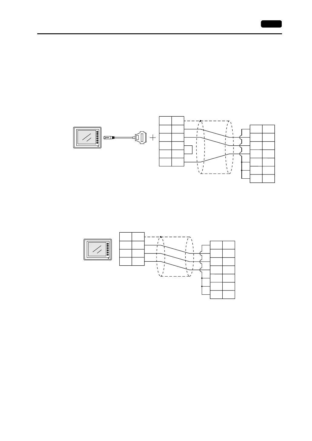
There are two connection methods.
• With MJ2-PLC
One method uses an adaptor MJ2-PLC for connection between MJ2 and the D-sub 25-pin
connector plus a PLC communication cable.
For connection of a PLC communication cable, refer to the CN1 pin arrangement.
• With V6-TMP
Refer to the PLC wiring diagram and the MJ2 pin arrangement.
Example: Connecting to MITSUBISHI A1SJ71UC24-R2
PLC
1
2
3
4
5
7
RD
SD
RS
CS
DR
SG
CD
1
2
3
5
6
7
8
FG
SD
RD
RS
CS
SG
MJ2
MJ2-PLC
D-sub 25-pin (male)
D-sub 9-pin (male)
V series PLC communication cable
PLC
RD
SD
RS
CS
DR
SG
CD
1
2
3
5
6
7
8
SG
SD
RD
SG
MJ2
SHELL
8
7
5
RJ-45 8-pin
V6-TMP
D-sub 9-pin (male)
Example: Connecting to MITSUBISHI A1SJ71UC24-R2