1-6 1. Before Connecting to PLC
MJ2 (V706 only)
*1 Switch between RS-232C and RS-422 for pin Nos. 1, 2, 7, and 8 with the slide switch on the MONITOUCH.
For more information, refer to “Slide Switch.”
*2 The maximum current for the output power supply (+5 V) is 150 mA when MJ1 or MJ2 is used.
Slide Switch
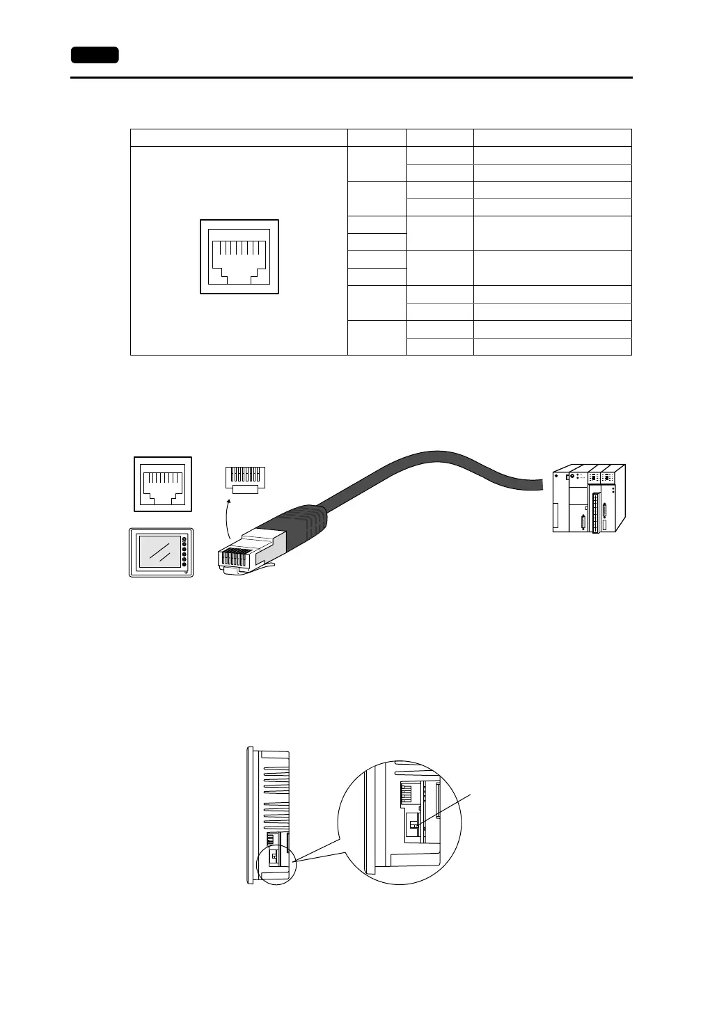
• Whether MJ2 is used as an RS-232C or RS-422 (4-wire) port is selected with the slide switch.
Before connecting a V706 to a PLC, check that the switch is set to the correct side.
• The slide switch is adjacent to the DIP switch on the side of the V706.
The switch is factory-set to RS-422. When RS-422 is selected, the slide switch is in the lower
position. To select RS-232C, slide the switch to the upper position.
MJ2 Pin No. Signal Name Contents
1
Not used Not used
+SD RS-422 + send data
2
Not used Not used
−SD RS-422 − send data
3
+5 V
Externally supplied +5 V
Max. 150 mA
4
5
SG Signal ground
6
7
RD RS-232C receive data
+RD RS-422 + receive data
8
SD RS-232C send data
-RD RS-422 − receive data
12345678
*1
*1
*2
*1
*1
PLC
87654321
12345678
RJ-45 8-pin
Pin arrangement
on the cable
* The pin arrangement shown above assumes
the cable is viewed as shown in the figure.
Pin arrangement on
the MONITOUCH
Side View
Slide switch
Lower position: RS-422 (4-wire)
Upper position: RS-232C