Documentation HERMA 500
1.10 GB (2019/02/28)
7
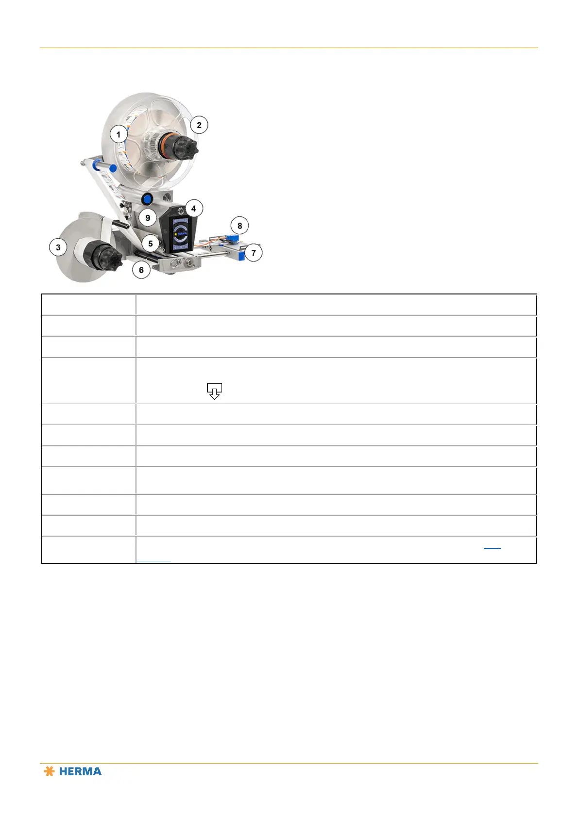
Applicator Overview
1
Unwinder (mechanical unwinder shown here; motorised unwinder also possible)
2
Counterholder (only required for vertical applicators)
3
Rewinder (mechanical rewinder shown here; motorised rewinder also possible)
4
Dispense button above the display (in the rest of these instructions and during
Ethernet-based remote control of the applicator, this button is represented by the
following icon: )
5
Label web brake
6
Clamping plate on transport roller
7
Dispensing beak (sample configuration)
8
Label sensor (FS03 shown here; forked light barrier (optical or ultrasonic) also
possible)
9
Base unit
A loop module can also be used in certain configurations. No image. See this
section.