4.35 Caster Assembly—New Brake Style
Chapter 4: Removal, Replacement, and Adjustment Procedures
Page 4 - 90 Affinity® Three Birthing Bed and Affinity® Four Birthing Bed
Service Manual (MAN272 REV 4)
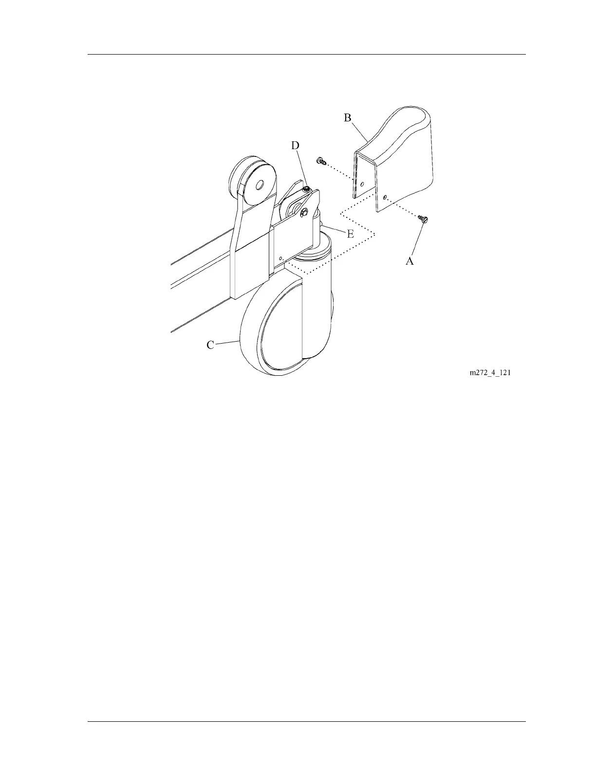
Figure 4-44. Caster Assembly
Replacement
1. Do the removal procedure in reverse order.
For B/C/D model beds, the new brake/steer caster could have 2 or 4 bolt holes
in the stem. If the stem has a green dot on it, the green dot faces the head-end
of the bed during installation.
2. To make sure the caster (C) rolls and swivels freely, and all brake and steer
functions work correctly, do the “Brake and Steer Caster Adjustment” on
page 4-81.
The brake/steer casters with the green dot will lock in the trailing position only.
Brake and Steer Caster Adjustment
For brake only casters, do steps 1 through 8 below. For steer casters, do all
steps.
1. Set the brake/steer pedal to the neutral position.