4.6 Foot Drive Motor Assembly
Chapter 4: Removal, Replacement, and Adjustment Procedures
Page 4 - 20 Affinity® Three Birthing Bed and Affinity® Four Birthing Bed
Service Manual (MAN272 REV 4)
9. Deactivate the lockout function, and lower the foot section until the foot
yoke is resting on the 2" x 4" pieces of lumber.
10. Using a ratchet and T25 Torx®
1
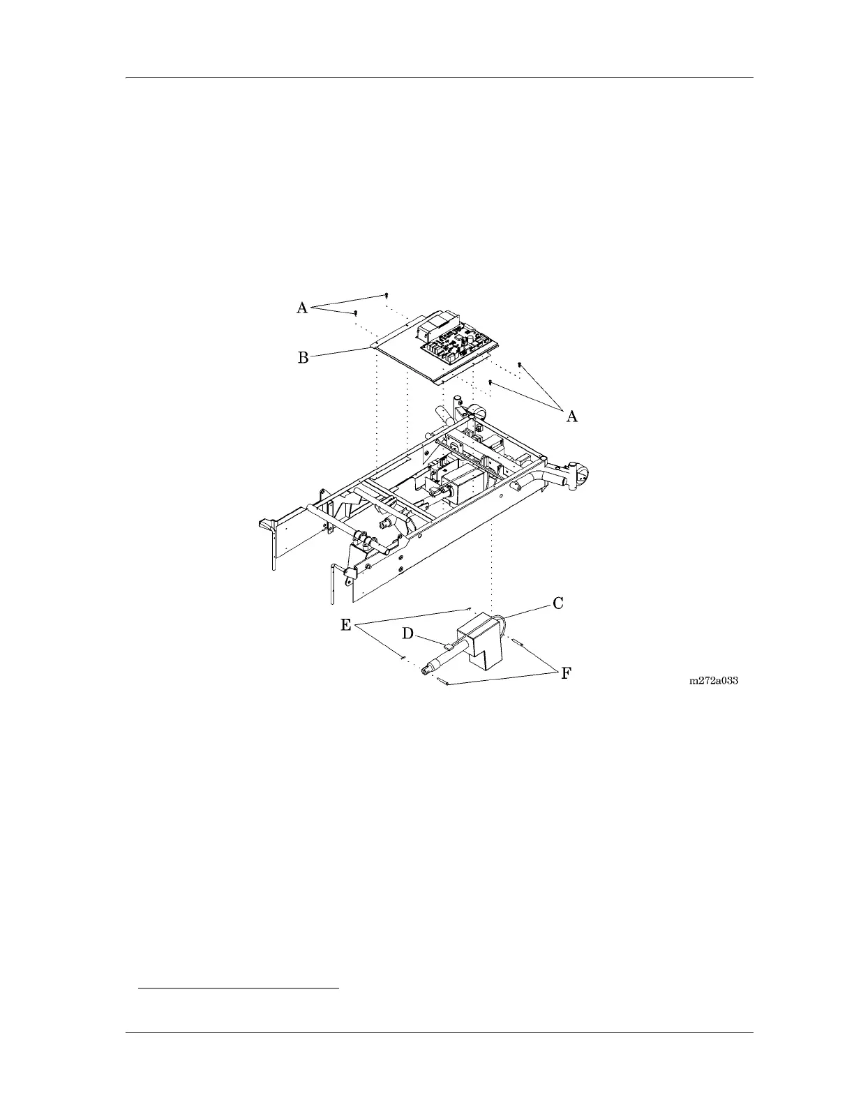
head bit, remove the four screws (A)
securing the electronics plate weldment (B) to the bed frame (see figure 4-
9 on page 4-20).
Figure 4-9. Foot Drive Motor Assembly
11. To improve access to the foot drive motor assembly (C) on the left side,
carefully lift and move the electronics plate weldment (B) to the patient’s
right-hand side of the bed.
12. Unplug the foot drive motor assembly (C) power cable (D) from logic
control P.C. board connector P6.
13. Using the needle nose pliers, remove two cotter pins (E) from the two
clevis pins (F) that secure the foot drive motor assembly (C) to the bed
frame.
14. Remove the two clevis pins (F) from the foot drive motor assembly (C),
and from the bed frame.
1. Torx® is a registered trademark of Textron, Inc.