8.2 Connect and be sure to tighten the screws on the connector
141
8
Chapter 8 Controlling the Instrument From a Computer
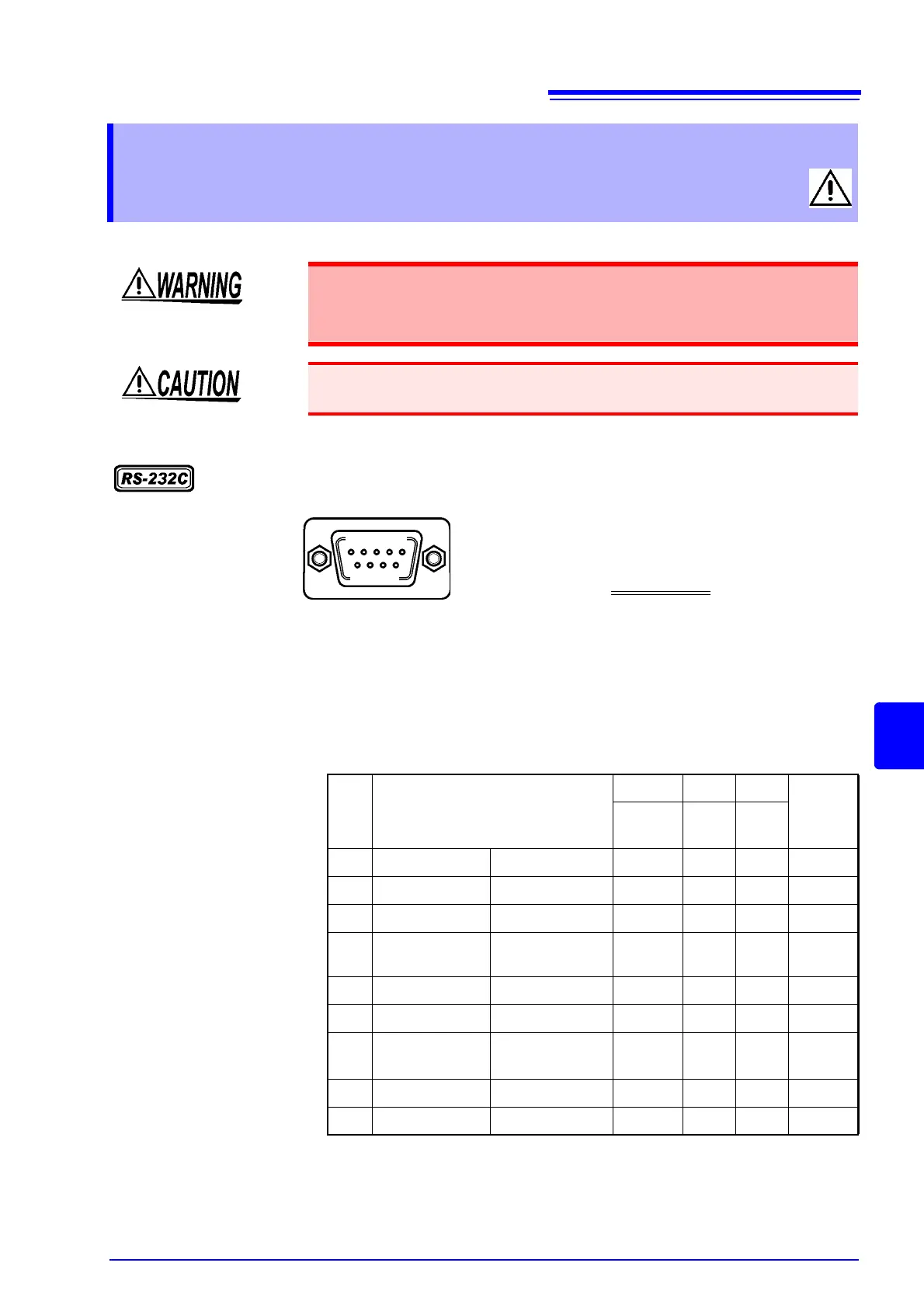
RS-232C connector
8.2 Connect and be sure to tighten
the screws on the connector
• Always turn both devices OFF when connecting and disconnecting an
interface connector. Otherwise, an electric shock accident may occur.
• To avoid damage to the instrument, do not short-circuit the terminal and
do not input voltage to the terminal.
Failure to fasten the connectors properly may result is sub-specification perfor-
mance or damage to the equipment.
1 2 3 4 5
Connect the RS-232C cable.
To connect the HiTESTER to the controller
(DTE), use a crossing cable
compatible with the
connectors on both the HiTESTER and the con-
troller.
6 7 8 9
D-sub 9Pin male connector
with M2.6 set screws
The I/O connector is designed for the terminal (DTE).
The HiTESTER uses pins Nos. 2, 3, and 5. All other pins are not used.
Pin
No.
Functions CCITT EIA JIS Signal
Name
Circuit
No.
Code
Addr.
Code
Addr.
1 Not used
2 Receive Data
Receive Data 104 BB RD RxD
3 Send Data
Send Data 103 BA SD TxD
4 Data Terminal
Ready
Data Terminal
Ready
108/2 CD ER DTR
5 Signal Ground Signal Ground
102 AB SG GND
6 Not used
7 Request to
Send
Request to Send 105 CA RS RTS
8 Clear to Send
Clear to Send 106 CB CS CTS
9 Not used