9.1 Description of Signals
246
9.1 Description of Signals
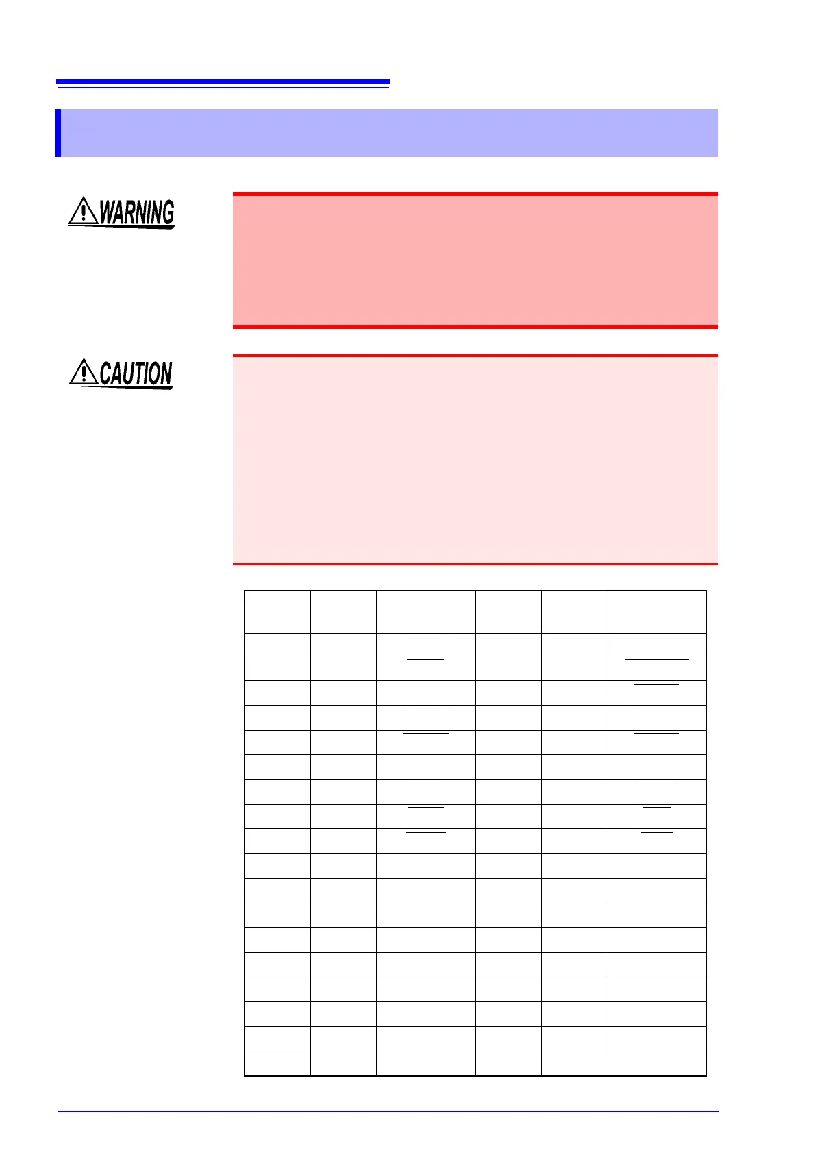
To prevent electrical hazards, observe the following cautions:
• Turn off the instrument's power switch before connecting a cable to the
terminal. Ensure secure connection to prevent the cable from discon-
necting during operation and contacting a conductive part (e.g., chassis,
test leads).
• Note that INT.GND is grounded. Therefore, electric potential in the con-
troller may result in short-circuiting and cause an electrical hazard.
To prevent damage to the instrument, observe the following cautions:
• Do not input voltage or current exceeding the rating to the EXT I/O terminal.
• When using a relay, be sure to install a diode for absorbing counter-electromo-
tive force.
• Do not short-circuit between the input and output terminals in the EXT I/O.
• Do not short-circuit between INT.DCV and INT.GND.
• Be sure to ground the equipment connected to the EXT I/O terminal. Failure to
provide protective earthing may damage the insulation of the measurement
system.
• The EXT I/O terminal is operable only when the measurement screen is dis-
played.
Pin No.
Input/
output
Signal line
name
Pin No.
Input/
output
Signal line
name
1 Input START
19 - (Reserved)
2 Input STOP
20 Input KEYLOCK
3 - (Reserved) 21 Input LOAD0
4 Input LOAD1 22 Input LOAD2
5 Input LOAD3 23 Input LOAD4
6 - (Reserved) 24 - (Reserved)
7 Output TEST
25 Output MEAS
8 Output PASS 26 Output FAIL
9 Output T-FAIL 27 Output LOW
10 - (Reserved) 28 - (Reserved)
11 Input EXT.DCV 29 Output INT.DCV
12 Input EXT.DCV 30 Output INT.DCV
13 Input EXT.DCV 31 Output INT.DCV
14 Input EXT.DCV 32 Output INT.DCV
15 Input EXT.COM 33 Output INT.GND
16 Input EXT.COM 34 Output INT.GND
17 Input EXT.COM 35 Output INT.GND
18 Input EXT.COM 36 Output INT.GND