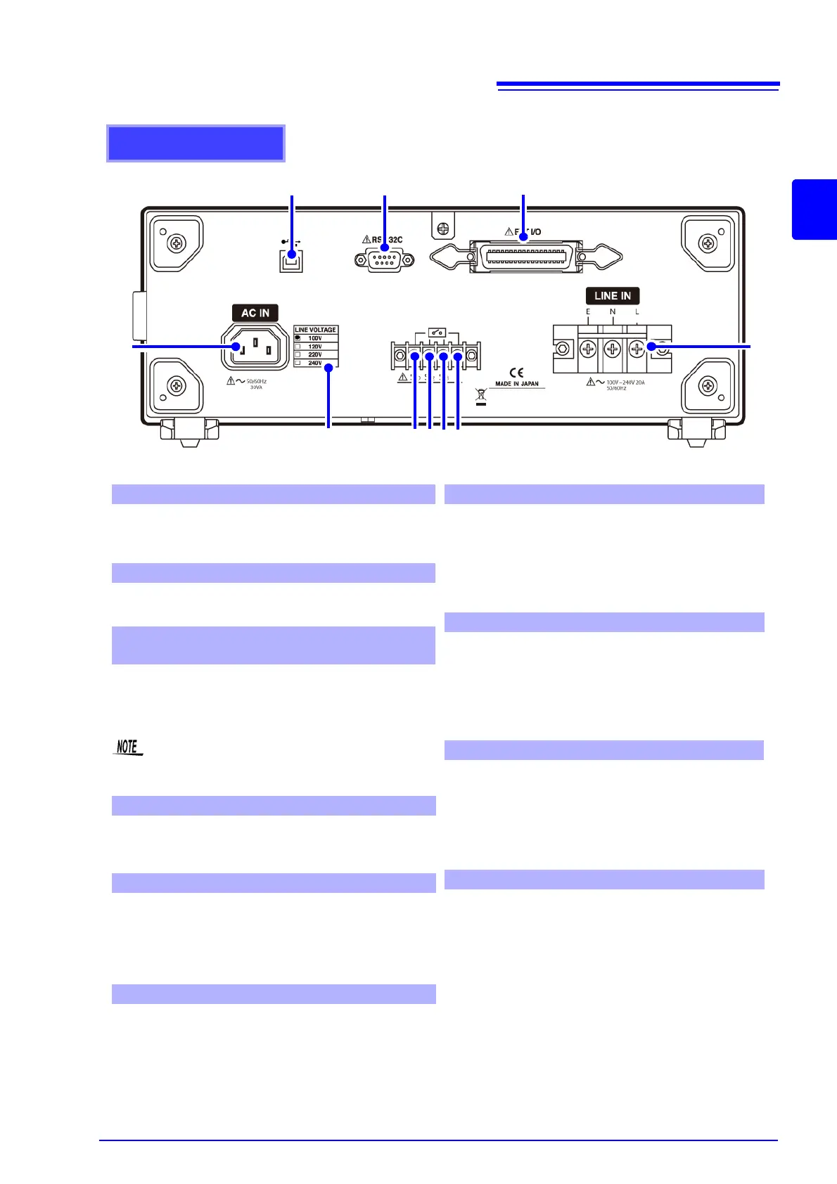
Rear Panel
Used for input of the power supply to operate the
instrument.
Used to connect the power cord provided.
Marked with a black dot (
) in the power line voltage
specification section.
Used for input of the power supply for equipment
under test.
Used to connect the power cord provided.
(Maximum rating: 250 V/20 A)
Correct measurements are not made when no
voltage is input to [LINE IN].
See (p. 33)
Input/output terminal for external control.
(The proper connector is required for connection.)
See (p. 245)
Used to connect an RS-232C cable or 9444 Con-
nection Cable (for the 9442 Printer).
(The 9442 Printer, 9444 Connection Cable,
and other accessories are optional products.)
See (p. 139)
Used to connect a USB cable.
(The USB terminal provides communication func-
tions but no storage capacity.)
See (p. 139)
1. Power inlet [AC IN]
2. Power source rating
3. Inlet for power line of equipment under test
[LINE IN]
4. EXT I/O connector
5. RS-232C connector
6. USB connector
Terminal for connecting function ground terminal
and power supply system for measurement. Con-
nect to E (earth) for [LINE IN].
Enables connection to earth during leakage current
measurements. (only ST5540)
See (p. 35)
Terminal for connecting patient connection to
ground for power supply circuit for measurement.
Connect to E (earth) for [LINE IN].
Enables connection to earth during leakage current
measurements. (only ST5540)
See (p. 35)
Terminal providing ground connection for metal
accessible part not protectively earthed. Connect to
E (earth) for [LINE IN]. Enables ground connection
during leakage current measurements. (only
ST5540)
See (p. 35)
Connected to E (earth) of [LINE IN].
This is a permanent connection that cannot be
changed.
*
Setting enabled only when B1 or B2 network
is selected.
7. S10 terminal*
8. S12 terminal*
9. S13 terminal*
10. E terminal
1
2
3
4
5
6
7
8
9
10