9.5 Timing Chart
252
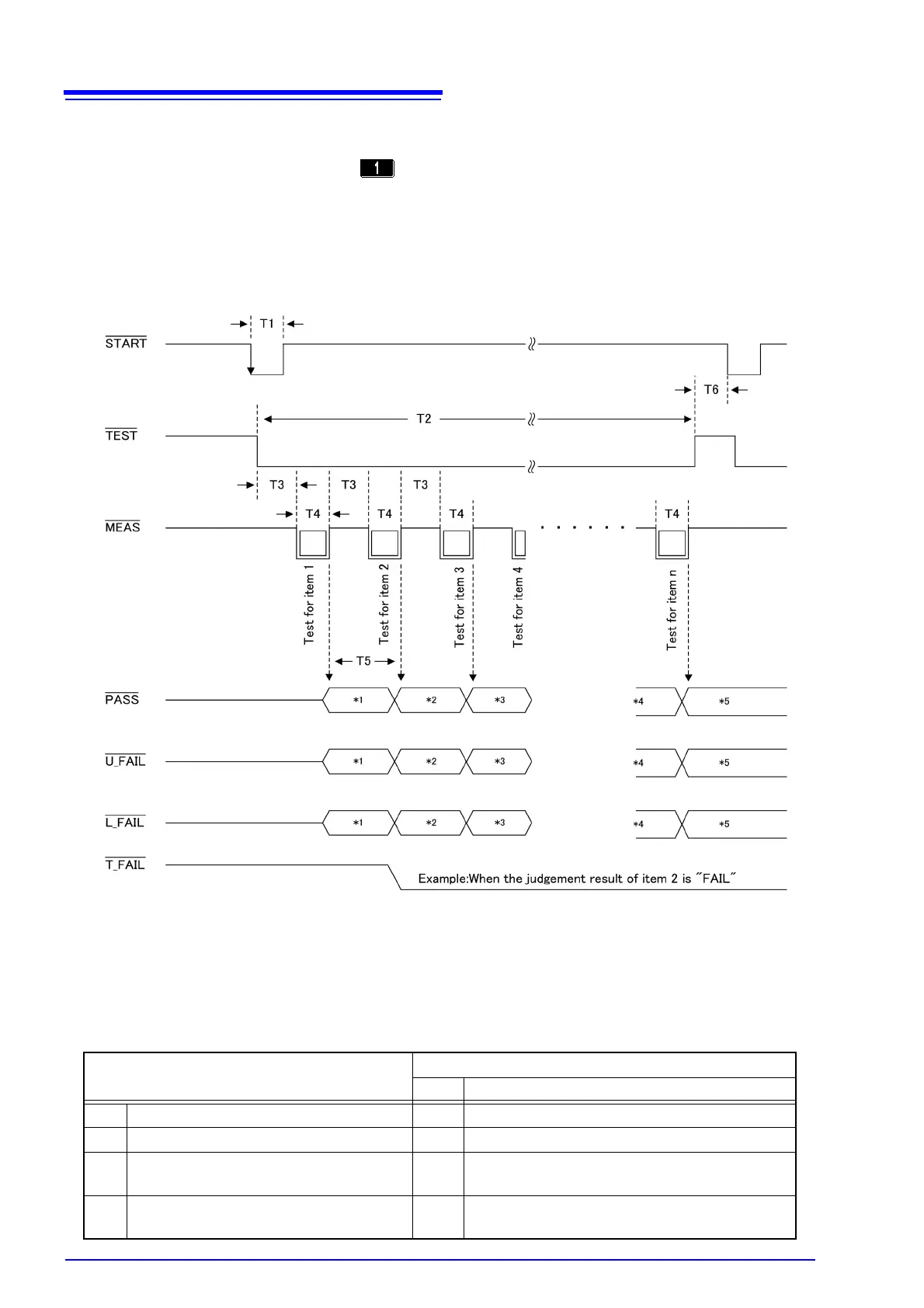
The following shows the output signal timing chart for automatic measurement.
The number of measurement items (n) varies depending on [number of polarity conditions] x [num-
ber of equipment status] set with displayed on the automatic measurement setting screen.
(Example)
Polarity : Positive polarity ON, negative polarity ON......2
Equipment status : Normal condition ON,
earth conductor disconnection ON ................2
With the above settings, the number of measurement items (n) is 4 (2 x 2 = 4).
*1 : Judgement result of item 1
*2 : Judgement result of item 2
*3 : Judgement result of item 3
*4 : Judgement result of item (n - 1)
*5 : Judgement result of item n
Description
Time
MIN MAX
T1 Measurement start signal pulse width 1 ms –
T2 Automatic measurement time 2 s (T3 + T4) x number of measurement items
T3 Wait time between setting items 1 s According to measurement delay setting for
automatic measurement
T4 Measuring time of each setting item 1 s According to measuring time setting for auto-
matic measurement