E1 Series Servo Drive User Manual Electrical Planning
HIWIN MIKROSYSTEM CORP. 5-25
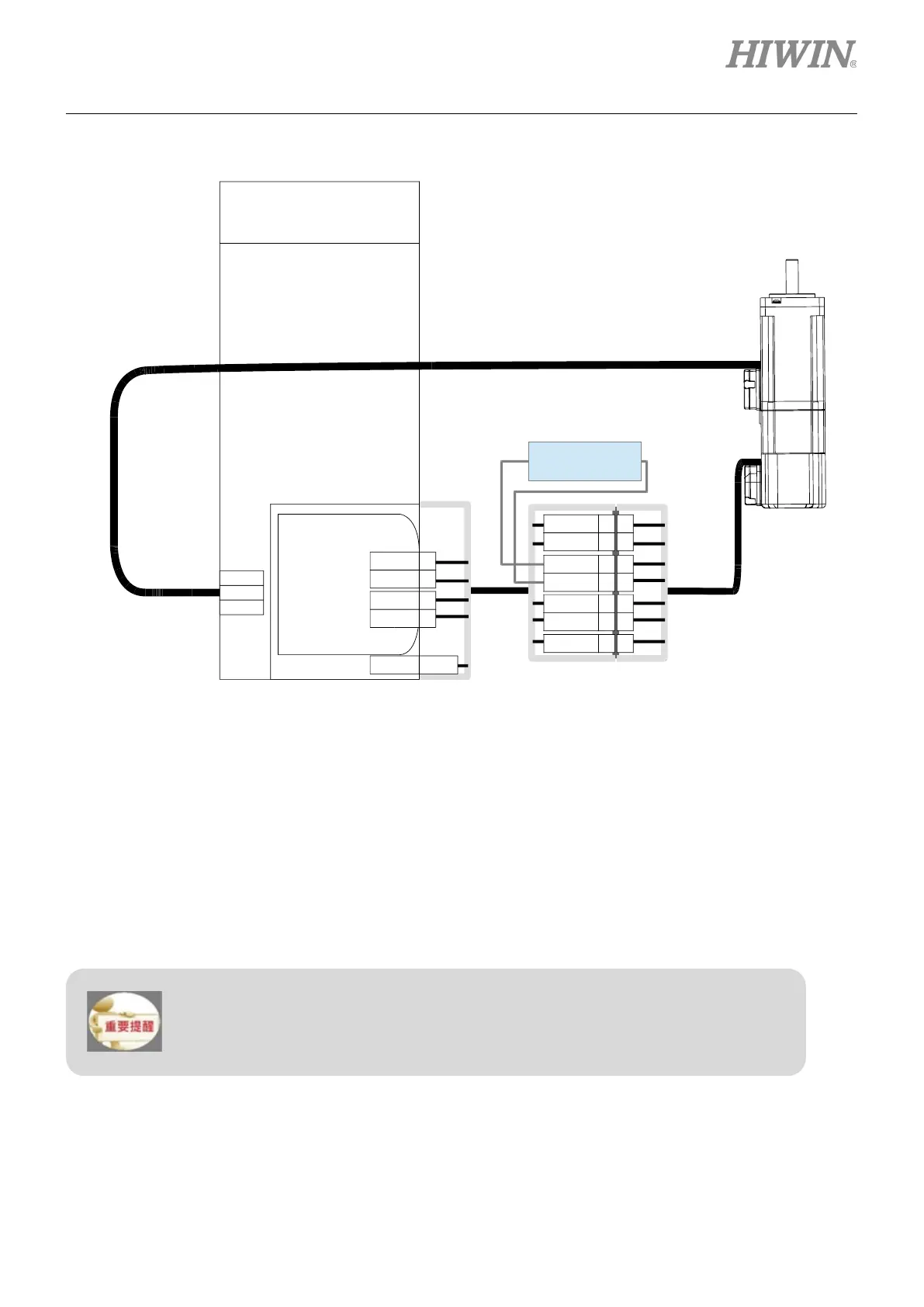
While using multi-turn absolute encoder to record motor revolutions, please install battery.
Figure5.4.3.2
Note:
(1) The battery must not be installed at the motor side to prevent interference with the machine. The battery
should be installed at the servo drive side and inside the control box.
(2) For information of encoder extension cable, please refer to table 16.1.2.1 in section 16.1.2.
(3) For information of battery box and battery, please refer to table 16.2.4.1 in section 16.2.4.
5.4.4 Wiring for brake
HIWIN
E1 Series Drive
CN7
+5 Vdc
1
0 Vdc 2
PS + 3
PS - 4
FG Shield
1
2
5
6
W
V
U
CN2
Battery
1
2
5
6
+5 Vdc
0 Vdc
99Shield
VB
GND
+ -
3.6 VDC
7
8
7
8
PS(SD)
+
PS(SD) -
The default pins for brake control output (BK) signal are CN6-40/12 (O5). To change
pin assignment, please refer to section 6.8.2.
While using brake, DC 24 V for brake and power for I/O signals (CN6) must not share
the same power supply to avoid false operation.
 Loading...


