E1 Series Servo Drive User Manual Monitoring
HIWIN MIKROSYSTEM CORP. 11-7
11.4 Using measuring instrument
11.4.1 Changing scale and offset
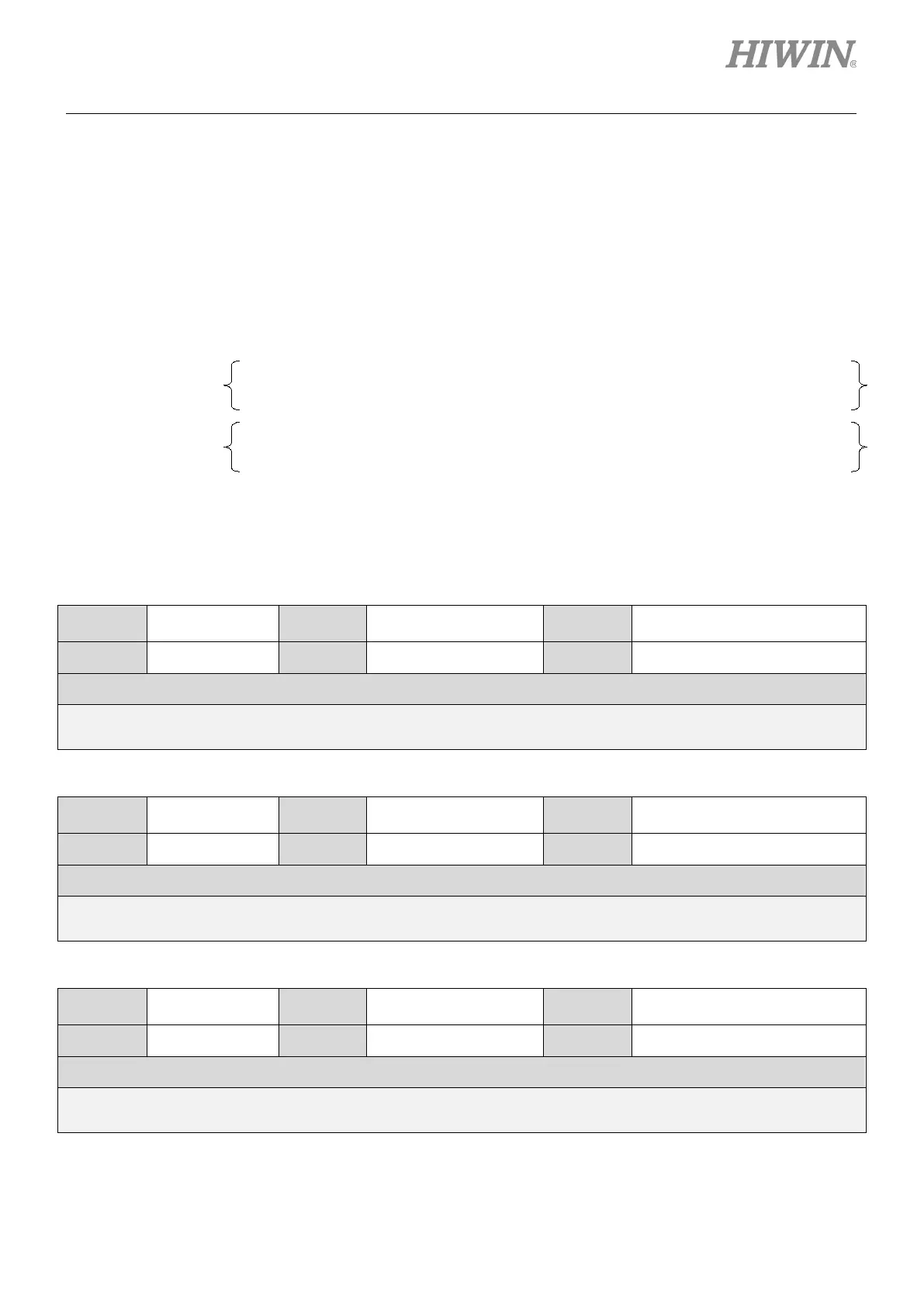
Users can change the scales and offset voltage of analog monitor 1 and analog monitor 2. The
relationship of scale, offset voltage and output voltage is shown in figure 11.4.1.1.
The related parameters are provided as below.
Table11.4.1.1
Parameter Pt550 Range -10000~10000
Position mode, velocity mode
and torque mode
Default 0 Effective Immediately Unit 0.01 V
Description
Analog monitor 1 offset voltage
Table11.4.1.2
Parameter Pt551 Range -10000~10000
Position mode, velocity mode
and torque mode
Default 0 Effective Immediately Unit 0.01 V
Description
Analog monitor 2 offset voltage
Table11.4.1.3
Parameter Pt552 Range -10000~10000
Position mode, velocity mode
and torque mode
Default 100 Effective Immediately Unit x 0.01
Description
Analog monitor 1 scale
Analog monitor 1
output voltage
=
Analog monitor 1 signal selection
(Pt006 = t.□□xx)
╳
Analog monitor 1 scale
(Pt552)
+
Analog monitor 1 offset
voltage (Pt550)
Analog monitor 2
output voltage
=
Analog monitor 2 signal selection
(Pt007 = t.
□□xx)
╳
Analog monitor 2 scale
(Pt553)
+
Analog monitor 2 offset
voltage (Pt551)
 Loading...


