E1 Series Servo Drive User Manual Application Function
HIWIN MIKROSYSTEM CORP. 8-3
8.1 I/O signal settings
8.1.1 Digital input signal allocation
This section describes how to allocate digital input signals to the desired pins. Each pin is allocated with
one default digital input signal when the servo drive is shipped out. The allocated digital input signal of
each pin varies with the selected control mode. Users can choose to use the default setting or allocate
digital input signals by themselves.
Use the default setting
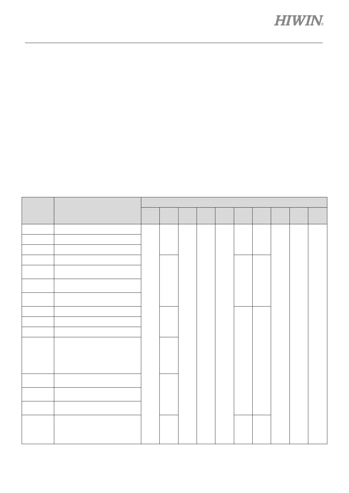
The default allocations of digital input signals in different control modes are listed in table 8.1.1.1.
Use Pt000 to select control mode and set Pt513 to t.0 to use the default setting.
Table8.1.1.1
Pt000 =
t.X
Control Mode
CN6 Pin
33
(I1)
30
(I2)
29
(I3)
27
(I4)
28
(I5)
26
(I6)
32
(I7)
31
(I8)
9
(I9)
8
(I10)
0 Velocity mode
S-ON
P-CON
P-OT
N-OT
ALM-RST
P-CL
N-CL
HOM
MAP
FSTP
1 Position mode
2 Torque mode
3 Internal velocity mode
SPD-D
SPD-A
SPD-B
4
Internal velocity mode
↔Position mode
5
Internal velocity mode
↔Velocity mode
6
Internal velocity mode
↔Torque mode
7 Position mode↔Velocity mode
C-SEL
P-CL
N-CL
8 Position mode↔Torque mode
9 Torque mode↔Velocity mode
A Internal position mode
P-CON
B
Internal position mode
↔Position mode
C-SEL
C
Internal position mode
↔Velocity mode
D
Internal position mode
↔Torque mode
E
Internal velocity mode
↔Internal position mode
SPD-D
SPD-A
SPD-B

 Loading...


