THINPREP 2000 INSTALLATION
2.8
ThinPrep 2000 Processor Operator’s Manual
5. To remove the PMC, simply depress the black button at the top of the receptacle and gently
remove the PMC.
CONNECTING THE POWER CORD
Caution:
Turning the power on before instructed to do so can damage the instrument and inval-
idate your warranty.
1. Ensure that the power switch, located on the rear of the ThinPrep 2000 Processor, is in the “O”
(Off) position. For “Off,” the top half of the toggle power switch is in the “out” position (pro-
trudes).
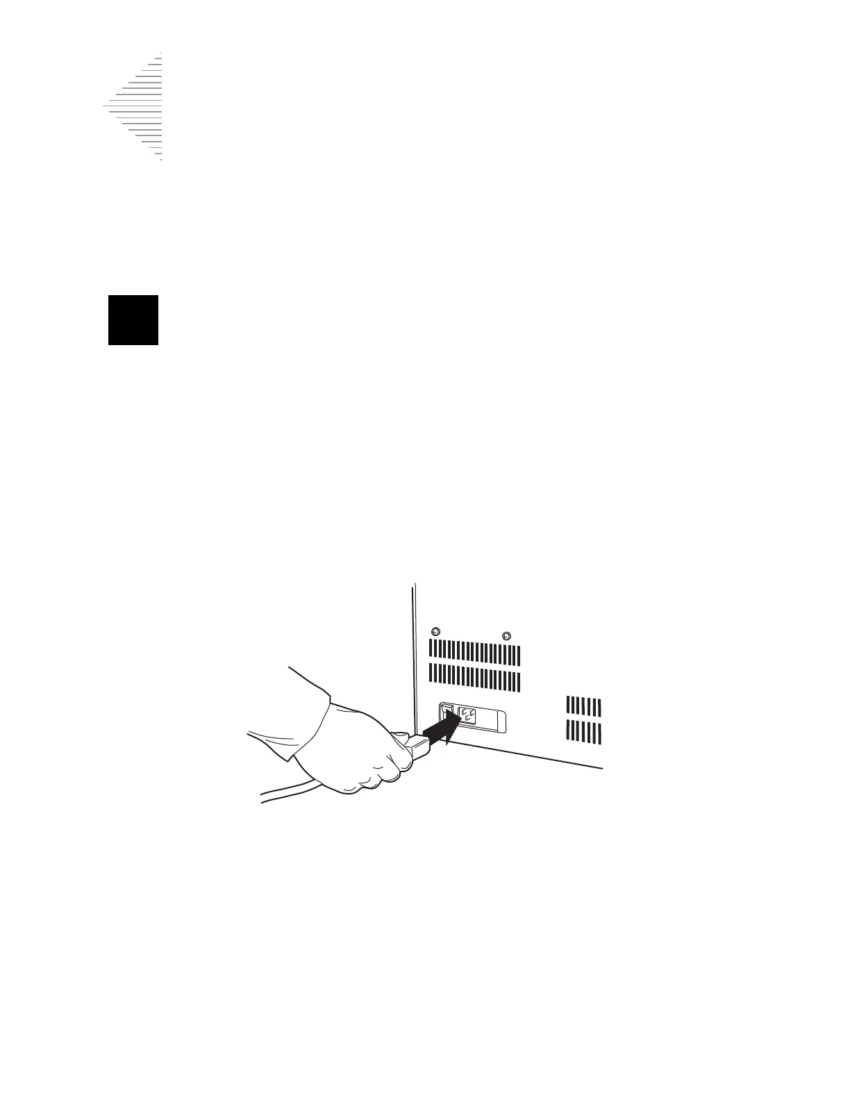
2. Insert the power cord into the power receptacle located on the rear of the ThinPrep 2000 proces-
sor next to the power switch. Refer to Figure 2-5.
3. Connect the power cord to a 3-prong grounded outlet.
Figure 2-5 Connecting the Power Cord
4. The ThinPrep 2000 processor is designed with an automatic line voltage detection feature. This
feature eliminates the need to manually change the system line voltage setting to meet your spe-
cific requirements. The instrument will automatically adapt to any line voltage between 100–
120 VAC and 220–240 VAC.
Caution:
Do not attach a cable to the 9-pin connector on the rear of the instrument. This connec-
tor is available for diagnostic purposes only.
Caution:
The ThinPrep 2000 processor is fused internally. No user accessible fuse is available.