7.1 Use of RS232/RS485/UART
Application
EC350 is capable of communicating with a number of types of external devices, such as cellular or
landline modems, and RTUs. EC350 supports the following protocols: MI Protocol, Modbus RTU, Modbus
ASCII. The description of those protocols is beyond the scope of this manual, although a basic discussion
of Modbus operation is presented later in this chapter. This section describes the physical connections
and instrument configuration parameters that are required.
Connections
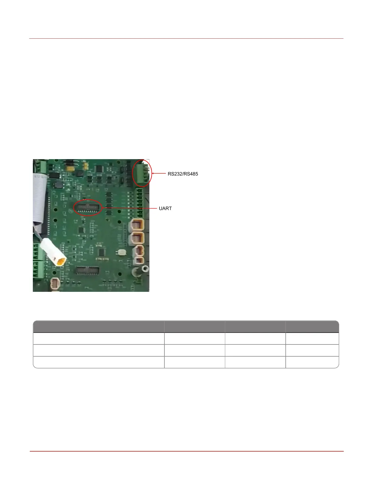
Wiring connections are made to TB4, see below:
For RS-232, only 3-wire communications is supported. The RS-232 and RS-485 standard specifications
should be consulted for the proper wire type, maximum cable length, etc.
RS232 RS485 UART
TXD (Transmit Data) Pin 1 Line A Pin 6
RXD (Receive Data) Pin 2 Line B Pin 4
GND (Ground) Pin 5 Pin 5 Pin 2
Jumpers
In addition to wiring, jumpers on JP1 and JP2 must be properly positioned. For RS-232, both jumpers
must be set to B and C as shown in the picture above. They must be placed on A and B for RS-485.
7 Remote Communications
7.1 Use of RS232/RS485/UART
Honeywell 2024
216
 Loading...