28 IFP-75/IFP-75HV Installation/Operation Manual — P/N LS10147-001SK-E:D 06/25/2021
Control Panel Installation Battery Power
4.3.1 Battery Accessory Cabinet
The Model RBB Accessory cabinet can be used when your backup batteries’ requirements use backup batteries that are too large to fit into
the main control panel cabinet. The RBB cabinet holds batteries up to the 35 AH size. The RBB dimensions are 16" W x 10" H x 6" D (40.64
cm W x 25.4 cm H x 15.24 cm D).
Installing the RBB Accessory Cabinet and Batteries
To properly install the accessory cabinet and backup batteries, follow these steps:
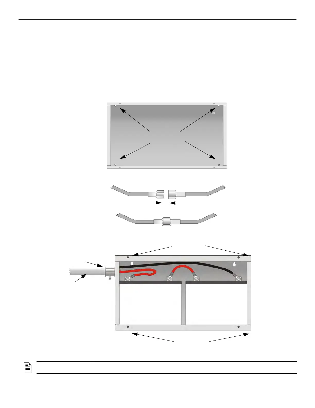
1. Mount the accessory cabinet. See Figure 4.5 for the four cabinet mounting holes.
• If mounting onto drywall the accessory cabinet must be mounted onto 3/4-inch plywood. This is necessary because the weight of the
batteries inside the accessory cabinet could cause the cabinet to pull away from the drywall.
• When mounting on concrete, especially when moisture is expected, attach a piece of ¾” plywood to the concrete surface and then
attach the RBB cabinet to the plywood.
• If you use the battery cable extenders, provided (P/N 140643), mount the RBB cabinet no more than 18" away from the main control
panel cabinet. This will ensure that the battery cables reach the battery terminals.
.
Figure 4.5 RBB Cabinet Mounting Holes
2. Connect the main control panel battery cables to the battery cable extenders as shown in Figure 4.6.
Figure 4.6 Splicing Control panel Battery Cable to RBB Battery Cable Extenders
3. Run extended battery cable from control panel cabinet through conduit to RBB cabinet. See Figure 4.7.
.
Figure 4.7 Battery Connections in the RBB Cabinet
conduit
conduit
coupler
++
--
RBB Cabinet
cover screws
RBB Cabinet
cover screws
NOTE: Figure 4.7 is an example of how the wire connections can be routed. However, any other cabinet knock-outs (on either the main control
panel or the RBB cabinet), that are not previously being used may be utilized to connect conduit between the two cabinets.

 Loading...


