22 IFP-75/IFP-75HV Installation/Operation Manual — P/N LS10147-001SK-E:D 06/25/2021
Prerequisites for Installation Calculating Current Draw and Standby Battery
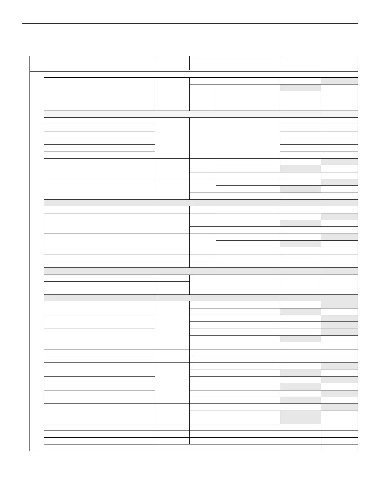
3.7.3 Current Draw Worksheet for SD SLC Devices
Use Table 3.4 to determine current requirements during the alarm/battery standby operation when the SD SLC devices are installed. You can
install up to 75 SD devices per panel.
1
Device # of Devices Current per Device
Standby
Current
Alarm
Current
For each device use this formula: This column X This column = Current per number of devices.
Fire Panel (Current draw from battery) 1 Standby: 165mA 165 mA
Alarm: 310mA 310 mA
Addressable SLC Devices
SD500-AIM Standby/Alarm: .30mA
5
mA mA
SD500-MIM mA mA
SD500-ARM mA mA
SD500-PS/SD500-PSDA mA mA
SD505-HEAT mA mA
SD505-PHOTO mA mA
SD500-ANM Aux. Pwr Standby: 8mA mA
Alarm: 60mA mA
SLC Standby/Alarm: .55mA mA mA
SD500-SDM Aux. Pwr Standby: 20mA mA
Alarm: 106mA mA
SLC Standby/Alarm: .55mA mA mA
SLC Accessory Bases
SD505-6RB Standby/Alarm: .082mA mA mA
SD505-6SB Aux. Pwr Standby: 1mA mA
Alarm: 32mA mA
SLC Standby/Alarm .082mA mA mA
SD505-DUCTR Aux. Pwr Standby: 20mA
2
mA
Alarm: 62mA
2
mA
SLC Standby/Alarm: .5mA mA mA
SD505-DTS-K None, included with SD505-DUCTR worst case.
SD505-DUCT SLC Standby/Alarm: .5mA mA mA
SLC Isolator Devices
SD500-LIM (100 max.) Standby/Alarm .092mA mA mA
SD505-6IB (50 max.)
Accessories Modules
RA-2000 Remote LCD Annunciator (8 max.) Standby: 25 mA mA
Alarm: 50 mA mA
RA-100 Remote LCD Annunciator Standby: 20 mA mA
Alarm: 25 mA mA
RA-1000 Remote LCD Annunciator Standby: 20 mA mA
Alarm: 25 mA mA
5824 Serial / Parallel Module (4 max.) Standby/Alarm: 45mA mA mA
5496 NAC Expander (8 max.) Standby/Alarm: 10mA mA mA
RPS-1000 Power Supply Standby/Alarm 10mA mA mA
5865-4 LED Annunciator
(with reset and silence switches)
(8 max.) Standby: 35mA mA
Alarm: 145mA mA
5865-3 LED Annunciator Standby: 35mA mA
Alarm: 145mA mA
5880 LED I/O Module Standby: 35mA mA
Alarm: 200mA mA
5883 Relay Interface (32 max.) Standby: 0mA mA
Alarm: 220mA
(22 mA per relay)
mA
SK-NIC Network Interface Card (1 Max.) Standby/Alarm: 21mA mA mA
SK-FML Fiber-Optic Multi Mode (1 Max.) Standby/Alarm: 53mA mA mA
SK-FSL Fiber-Optic Single Mode (1 Max.) Standby/Alarm: 79mA mA mA
Total System Current
Table 3.4 Current Calculation Worksheet for SD Devices

 Loading...


