44 IFP-75/IFP-75HV Installation/Operation Manual — P/N LS10147-001SK-E:D 06/25/2021
Control Panel Installation 5865-3 / 5865-4 LED Annunciator Installation
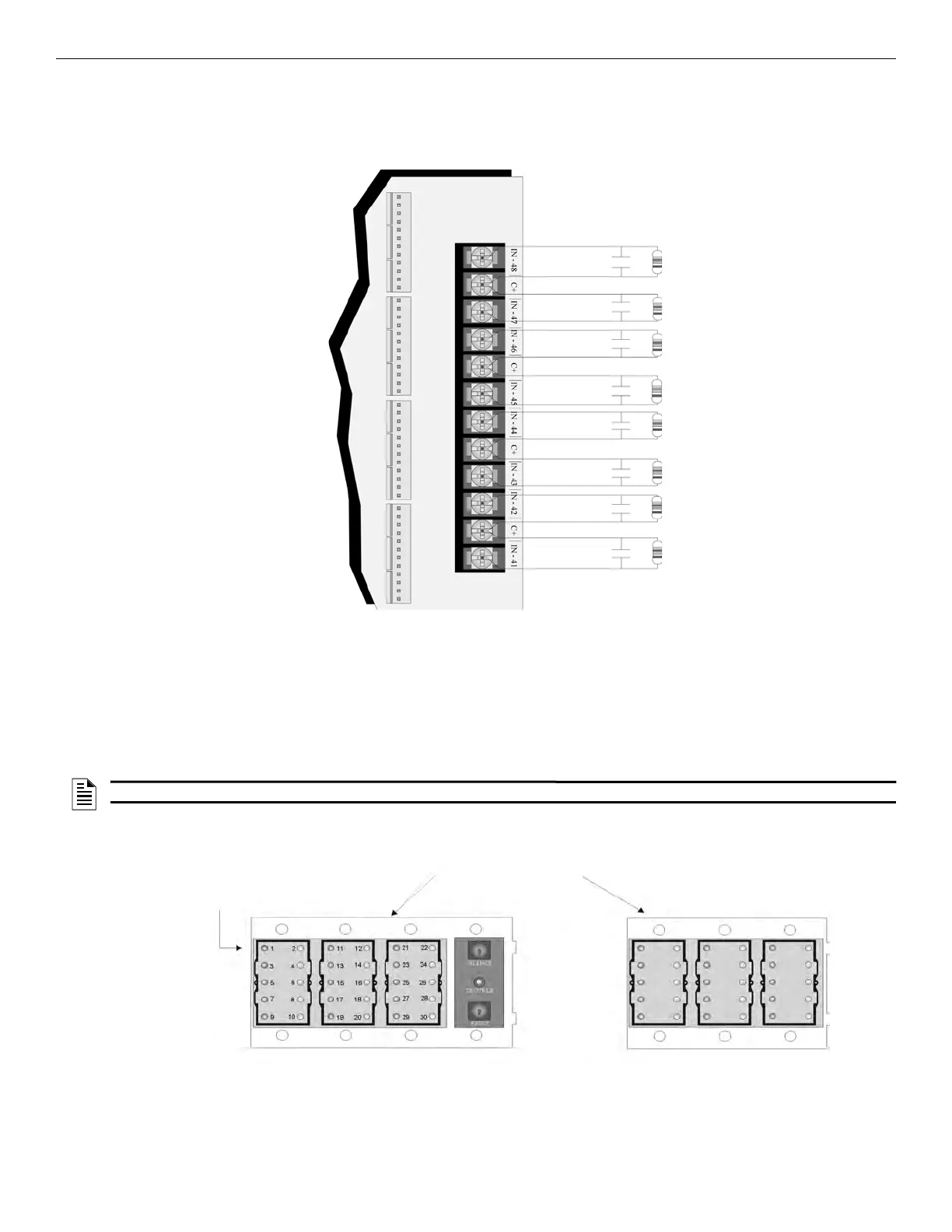
4.9.4 Dry Contact Wiring
The 8 input circuits on the 5880 board are used for monitoring the switch inputs. Any type of switch supported by the control panel can be
used with the 5880. For example, you can use the 5880 to monitor pull stations, water flow, tamper, reset, or silence switches.
Wire the dry contacts as shown in Figure 4.38. Notice that the grouping of the terminals; power terminals are shared by two inputs.
Figure 4.38 Dry Contact Wiring
4.10 5865-3 / 5865-4 LED Annunciator Installation
The 5865-3 and 5865-4 are LED annunciators. The 5865-4 has 30 mappable LEDs, remote silence and reset key switches, and a general sys-
tem trouble LED. The 5865-3 has 30 mappable LEDs only. These are arranged as 15 pairs of red (typically used for alarm) and yellow (typ-
ically used for trouble) LEDs.
The installation of the 5865-3 and 5865-4 is identical. The key switches and the trouble LED follow the behavior of other system annuncia-
tors and do not require any installation steps. The following sub-sections describe how to install the 5865-3 and 5865-4 hardware. Refer to
Section 6 for programming information.
Figure 4.39 5865-3 and 5865-4 Assembly (front view)
NOTE: This manual uses “5865” when referring to aspects of the 5865-3 and 5865-4 that are common to both models.
Note: Numbers indicate part
numbers for 5865.
They do ot appear on board
assembly.
Plexiglass plate mounted to the LED
board at the factory.
Do not remove.
Note: 5865
switches follow
the main FACP,
no installation or
programming
required.
5865-4 Board Assembly
5865-3 Board Assembly

 Loading...


