IFP-75/IFP-75HV Installation/Operation Manual — P/N LS10147-001SK-E:D 06/25/2021 55
Section 5: Networking Common Communicator List
5.1 Network System Hardware Features
5.1.1 Networked Panels
Networked
The IFP-75 panel can be networked to create a virtual system that is larger than 150 addressable points. Each additional IFP-75 provides
another 150 addressable points to the network total. For example, a network of 32 IFP-75 panels provides a maximum addressable point
capacity of 2,550 points (150 x 32= 4,800 IDP or SK devices).
5.1.2 Wiring Options to Connect Networked Panels
A networked site is a logical group of IFP-75 panels that behave as though the logical group is one large control panel. Each building is
referred to as a “site.” All panels in a site operate as a single panel. The control functions like reset, silence and alarm activation operate
across the entire site. There can be one or more logical sites within a networked system. Taken to the extreme, the maximum number of sites
within a network system is limited to the number of panels in the network with each site comprised of only one panel.
1. Fiber-Optic Single Mode - Use the SK-NIC and SK-FSL for up to 30dB loss of signal separation. SK-FSL connects to the network
using 9/125 micron single-mode fiber.
2. Fiber-Optic Multi-Mode - Use the SK-NIC and SK-FM for up to 8dB loss of signal separation SK-FML connects to the network using
62.5/125 micron multi-mode fiber.
3. Twisted-Pair Copper Wire - must use the SK-NIC to provide up to 3,000 feet of separation.
All methods of panel connectivity can be used within the same networked System. The network architecture provides true peer to peer capa-
bility allowing network survivability for all hardware that remains operational in the event of partial system failure..
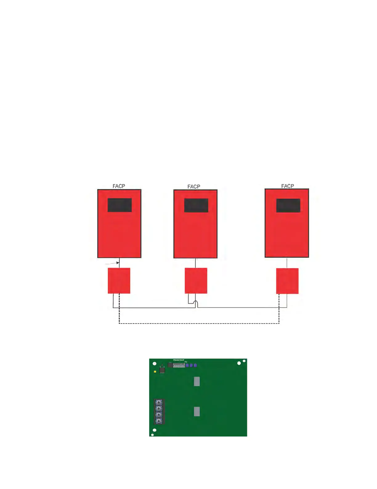
5.2 Direct Connect Wiring Option
When n networking in a group of IFP-75s you must use the SK-NIC to link the panels together. See Figure 5.1 for the external mounting of
SK-NIC option.
Figure 5.1 External SK-NIC Wiring Option
5.3 SK-NIC Wiring Options
Networking a group of IFP-75 require the use of a network interface card with each panel. The SK-NIC connects to other networked units
using unshielded, twisted-pair wiring or fiber-optic cable.
Figure 5.2 SK-NIC Network Interface Card
Class B wiring
Class A wiring
SK-NIC
SK-NIC
SK-NIC
In conduit, use
provided 2’
cable.

 Loading...


