114 IFP-75/IFP-75HV Installation/Operation Manual — P/N LS10147-001SK-E:D 06/25/2021
System Operation Releasing Operations
When you select a Single or Double Interlock Zone, releasing the System will automatically default the 5496 Intelligent Power
Module in the following System parameters:
• Output Group 2 is created.
Output Group 2 will be defaulted as an “Alarm” output group for all releasing zones. NAC [01:001] is assigned to Output
Group 2.
• Output Group 3 is created.
Output Group 3 will be defaulted as an “Pre-Alert” output group for all releasing zones. NAC [01:002] is assigned to
Output Group 3.
• Output Group 4 is created.
Output Group 4 will be defaulted as a “Release” output group for all releasing zones. NAC circuit [01:003] is assigned to
Output Group 4.
.
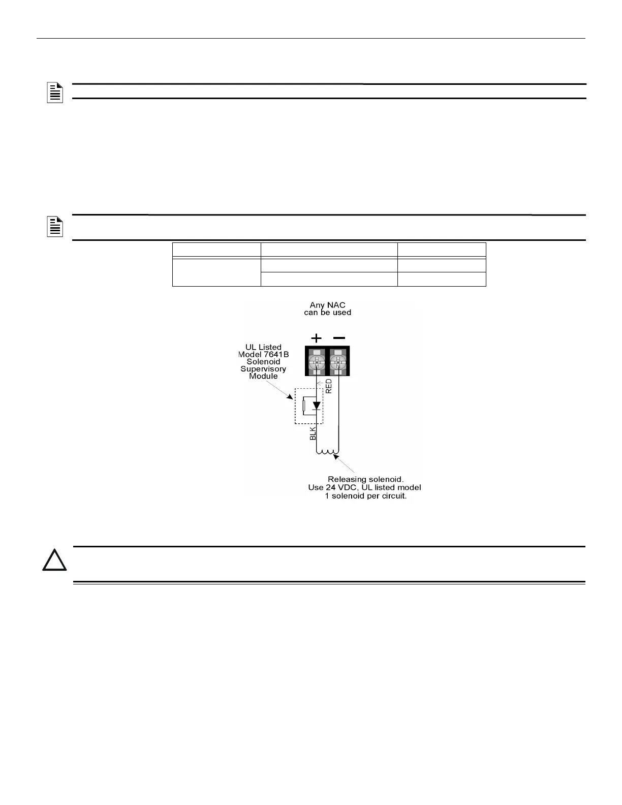
Figure 10.6 Wiring Configuration for Solenoid
10.7.1 Single Interlock Zone Releasing
A single interlock zone uses a minimum of two addressable detectors, and a designated manual release switch.
Conditions Required for an Pre-Alert Output Activation
If any single addressable detector is activated, the “Pre-Alert” output will activate and the “Pre-Alarm” output will deactivate.
This alerts the user that the initial stages required for a release condition are present. (Also refer to Table 10.5.)
NOTE 2: The defaults created can be modified through programming if desired.
NOTE 3: The Installer must define which input points will be used for detectors, manual release switches, or interlock/pressure
switches.
Manufacturer Part Number Rating
Asco T8210A107 24 VDC, 2.5A
8210G207 24 VDC, 2.5A
Table 10.4 Approved Releasing Solenoids
The Model 7641-L8
Must be located
at the solenoid.
*
CAUTION: ADDRESSABLE DEVICES ONLY:
Only addressable detectors can be used. No conventional detectors can be used. Each Single Interlock Zone input requires at
least one manual release switch.

 Loading...


