IFP-75/IFP-75HV Installation/Operation Manual — P/N LS10147-001SK-E:D 06/25/2021 39
RA-2000 Remote Annunciator Installation Control Panel Installation
4.7.1 Mounting the RA-2000
This Section of the manual describes mounting the remote annunciator. The annunciator can be flush or surface mounted.
Flush Mounting
This section of the manual describes flush mounting. Follow these steps to flush mount the RA-2000.
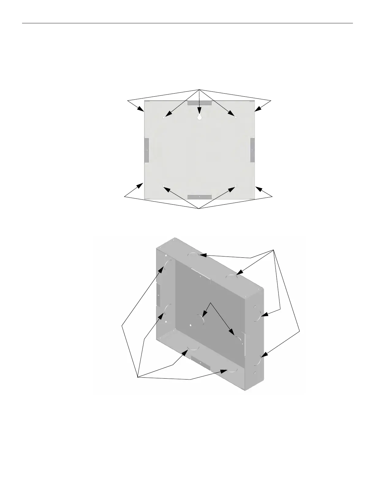
1. The back box dimensions are 9¼” W x 8 3/8” H. The minimum depth required is 2". The back box can be mounted prior to the
complete installation of the RA-2000 using any of the mounting holes shown in Figure 4.27.
Figure 4.27 Back Box Mounting Holes
2. Remove knockout holes as needed for wires. See Figure 4.28 for backbox knockout locations.
.
Figure 4.28 Back Box Knockout Locations
3. Wire the annunciator board to the main control panel. As described in Section 4.7.2.
4. Attach the annunciator and door assembly to the back box as shown in Figure 4.29 using the supplied screws.
Mounting Holes
Mounting Holes
Wire Knockouts
Wire Knockouts
Wire Knockouts

 Loading...


