40 IFP-75/IFP-75HV Installation/Operation Manual — P/N LS10147-001SK-E:D 06/25/2021
Control Panel Installation RA-2000 Remote Annunciator Installation
Figure 4.29 Attaching Annunciator / Door Assembly to Backbox
Surface Mounting
The Model RA-100TR red m and RA-2000GRAYTR gray trim ring kits are available for use when surface mounting the RA-2000..
1. Remove the desired knock out. See Figure 4.28.
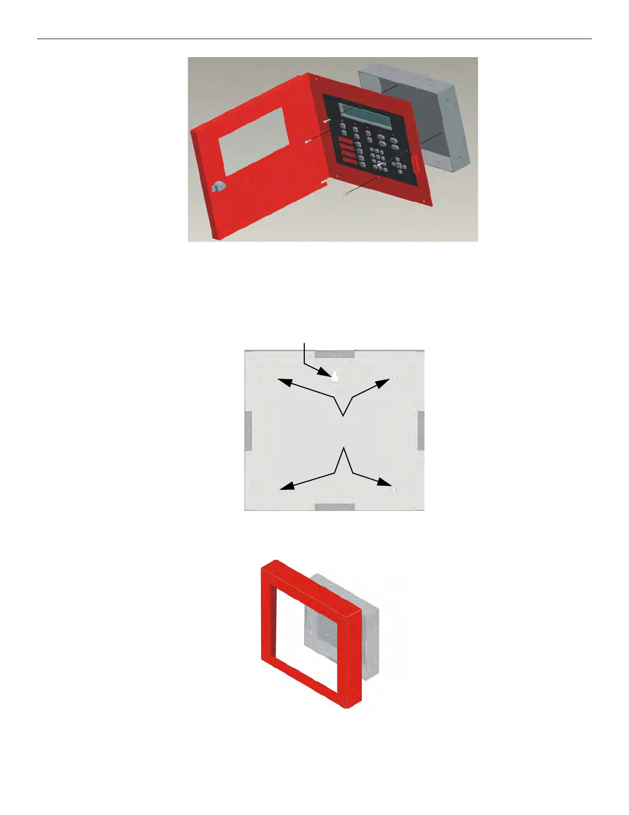
2. To properly mount the back box, insert a single screw into the key-shaped mounting hole. Do not tighten all the way. See Figure 4.30.
Place a level on top of the back box, with the back box level, insert the rest of the mounting screws.
Figure 4.30 Back Box Surface Mount Holes
3. Run wires to the control panel.
4. Place the trim ring over the back box as shown in Figure 4.31.
Figure 4.31 Installing Trim Ring
5. Attach the door assembly to the back box using screws provided.
6. After the SBUS wiring to the annunciator is complete, replace the electronic assembly in the back box. Place the bezel over the back
box and tighten the set screws on the bezel.
Key Shaped
Mounting Hole
Back Box
Mounting Holes

 Loading...


