IFP-75/IFP-75HV Installation/Operation Manual — P/N LS10147-001SK-E:D 06/25/2021 49
On-Board Relays (Conventional) Control Panel Installation
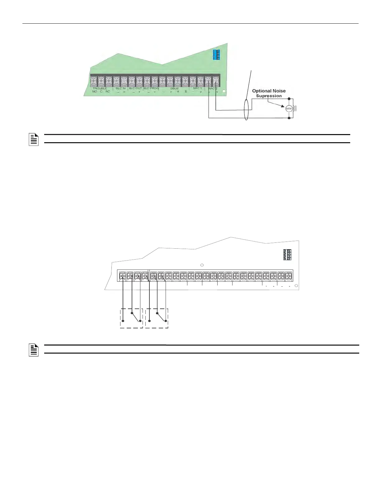
Figure 4.47 Example of an Auxiliary Power For Door Holder
Constant Power
Use constant power for applications that require a constant auxiliary power source. Power is always present at Constant circuits.
Resettable Power
Resettable power is typically used to power beam detectors, flame detectors and conventional 4-wire smoke detectors. For circuits selected
as Resettable, 27.4 volt power is always present at the terminals unless a System Reset occurs. If a System Reset occurs, the power automat-
ically becomes disconnected from the terminals for 30 seconds, then re-applied.
Sounder Sync Power
The Sounder Sync Power continuously outputs the System Sensor synchronization pattern and is intended for use with B200S/IV sounder
bases.
4.14 On-Board Relays (Conventional)
The control panel has two built-in programmable relays and a built-in trouble relay. All relays are Form C rated at 2.5 A @ 27.4 VDC Resis-
tive.
Figure 4.48 Location of Conventional Relay Circuits
4.14.1 Common Trouble Relay
The control panel has a dedicated Form C trouble relay built into the terminals labeled, TROUBLE. The relay provides a normally open and
a normally closed contact. The trouble relay will deactivate under any trouble condition. Form C rated at 2.5 A @ 27.4 VDC Resistive.
4.14.2 Programmable Relays
The control panel has two Form C programmable relays built into the terminals labeled, RELAY 1 or RELAY 2. Each relay provides a nor-
mally open and a normally closed contact.
To install one or two programmable relays, follow these steps.
1. Wire Relay 1 and/or Relay 2 as needed for your application. See Figure 4.48 for the location of the relay terminals.
2. Configure the relay through programming (see Section 8.2).
Non-Supervised
Power-Limited
cellul
NOTE: Figure 4.47 uses UL listed door holder Model 1400 from Door Control International as an example.
NO NC C
TROUBLE
RELAY 2
C NO NC
RELAY 1
C NO NC
CELLULAR AB S-S+
SLC IN
+
_
SLC OUT SLC PROG
+
_
+
_
SBUS
A
B
+
_
NAC 1
NAC 2
Connect to Power-Limited
Sources only
cellular S-
NOTE: The N.C. contact is the relay contact that is closed when the panel has power and there are no alarm or trouble conditions.

 Loading...


